BGP Best Path Selection

Studying the BSCI for CCNP can be hard for the reason that you need to memorize some stuff like BGP Best Path Selection. Few months ago I found this mnemonic helpful to memorize the BGP Path Selection Process. It's easy as eating pancakes and it is We Love Oranges AS Oranges Mean Pure Refreshment. By taking note of the letters in caps, one will immediately remember how BGP selects the best path by the list below.


“We Love Oranges AS Oranges Mean Pure Refreshment”

W Weight (Highest)
L LOCAL_PREF (Highest)
O Originate (local) routes that are advertise through the "network" command or redistributed from an IGP.
AS AS_PATH (shortest)
O ORIGIN Code (IGP > EGP > Incomplete)
M MED (lowest)
P Paths (External > Internal)
R RID (lowest)


That was easy! So from now on, every time you see an orange, BGP will always come in mind! Cheers!

MPLS Basics

One of the great advancements to enhance WAN services is MPLS. Originally, it was created to address the problems on ATM networks and thanks to Cisco and IETF, it has evolved to what it is today.

MPLS (Multiprotocol Label Switching) is a protocol that uses labels for packet switching. MPLS is agnostic of Layer 1 or Layer 2 protocols and can be used on any type of links. It inserts a 32-bit label in between the Layer 2 and Layer 3 headers which dubbed it as a Layer 2.5 protocol. These labels number range is 0-1,048,575. Labels 0-15 for reserved purposes therefore the usuable range is 16-1,048,575. The defaul range in Cisco routers is from 16 - 100,000 which is good enough for big enterprises.

MPLS requires a running IGP routing protocol with a full routing table. CEF must also be enable because FIB (Forwarding Information Base) and adjancency tables are needed to build the
LFIB (Label Forwarding Information Base). FIB is responsible for maintaning the next hops for the routes in the routing table while adjacency table is for the Layer 2 rewrite so that repetitive ARP requests will be avoided.

The process of how MPLS works starts by the routing protocol building the IP routing table. After that, based on the routing table the MPLS enabled router will now build its own mapping between destination ip to a label. Thirdly, using LDP (Label Distribution Protocol) the LSR's (Label Switch Routers or simply MPLS-enabled routers) in an MPLS networks share their assigned labels. Lastly, the LSR's build the LIB (Label Information Base), LFIB, and FIB based on the labels they received.

How to Configure MPLS in a Cisco Router

We have below a simple diagram of the network that will be used for this example. We will focus on the basics of configuration, some show commands and some "what if" scenarios.

Diagram:


Dynamips Configuration


autostart = true

ghostios = true
sparsemem = true
# MPLS Basics

[localhost]

[[7200]]
image = \Program Files\Dynamips\images\c7200-jk9o3s-mz.124-7a.bin
npe = npe-400
ram = 160

[[ROUTER R1]]
Se1/0 = R2 Se1/0
Se1/1 = R3 Se1/0

[[ROUTER R2]]
Se1/1 = R3 Se1/1

[[ROUTER R3]]

Basic Configurations


Start dynamips and apply the basic configuration below needed for this example. Just copy and paste everything below and it should be good.


R1
!
interface Serial1/0
ip address 192.168.12.1 255.255.255.0
no shut
!
interface Serial1/1
ip address 192.168.13.1 255.255.255.0
no shut

!
router ospf 1
log-adjacency-changes
network 0.0.0.0 255.255.255.255 area 0

R2
!
interface Serial1/0
ip address 192.168.12.2 255.255.255.0
no shut
!
interface Serial1/1
ip address 192.168.23.2 255.255.255.0
no shut
!
router ospf 1
log-adjacency-changes
network 0.0.0.0 255.255.255.255 area 0

R3
!
interface Serial1/0
ip address 192.168.13.3 255.255.255.0
no shut
!
interface Serial1/1
ip address 192.168.23.3 255.255.255.0
no shut
!
router ospf 1
log-adjacency-changes
network 0.0.0.0 255.255.255.255 area 0

Enabling MPLS


Once you have done this the OSPF adjacencies should be up and running. Now what we need to do is apply the necessary MPLS command to enable MPLS on network.


R1(config)#int se1/0
R1(config-if)#mpls ip
R1(config-if)#int se1/1
R1(config-if)#mpls ip

R2(config)#int se1/0
R2(config-if)#mpls ip
R2(config-if)#int se1/1
R2(config-if)#mpls ip

R3(config)#int se1/0
R3(config-if)#mpls ip
R3(config-if)#int se1/1
R3(config-if)#mpls ip


Once you have applied the single command "mpls ip" on the both sides of the link, an LDP adjacency will be formed and will display a log shown below:


*Feb 21 04:15:51.811: %SYS-5-CONFIG_I: Configured from console by console
*Feb 21 04:15:52.135: %LDP-5-NBRCHG: LDP Neighbor 192.168.13.1:0 (2) is UP


This means that MPLS is enabled on both sides and the neighbors are exchanging label information. The LFIB, FIB and LIB are created after the neighborships are formed.

Verifying MPLS Interfaces

Inorder to get which interfaces are mpls enabled the command "show mpls interfaces" is used. Operational state is "Yes" if the command "mpls ip" is enabled on the interface.


R3#sh mpls interfaces
Interface IP Tunnel Operational
Serial1/0 Yes (ldp) No Yes
Serial1/1 Yes (ldp) No Yes


Verifying LDP Neighbors


To know the LDP neighbors use "show mpls ldp neighbors". This will show the neighbors ID which is based on the highest ip address of the mpls enable interface., the LDP neighborship uptime, which interface it was discovered and the ip addresses of the MPLS enabled interfaces. Like OSPF, LDP's election of the ID is first chosen the highest ip address of the loopback interfaces and then the physical interfaces.


R3#sh mpls ldp neigh
Peer LDP Ident: 192.168.23.2:0; Local LDP Ident 192.168.23.3:0
TCP connection: 192.168.23.2.646 - 192.168.23.3.46832
State: Oper; Msgs sent/rcvd: 18/18; Downstream
Up time: 00:10:59
LDP discovery sources:
Serial1/1, Src IP addr: 192.168.23.2
Addresses bound to peer LDP Ident:
192.168.12.2 192.168.23.2
Peer LDP Ident: 192.168.13.1:0; Local LDP Ident 192.168.23.3:0
TCP connection: 192.168.13.1.646 - 192.168.23.3.26398
State: Oper; Msgs sent/rcvd: 6/6; Downstream
Up time: 00:00:39
LDP discovery sources:
Serial1/0, Src IP addr: 192.168.13.1
Addresses bound to peer LDP Ident:
192.168.12.1 192.168.13.1


Let's configure loopbacks for R1, R2 and R3. Using 1.1.1.1, 2.2.2.2 and 3.3.3.3 respectively and lets see what happends to the Peer LDP Ident.


R1#config t
R1(config)#int lo0
R1(config-if)#ip address 1.1.1.1 255.255.255.255

R2#config t
R2(config)#int lo0
R2(config-if)#ip address 2.2.2.2 255.255.255.255

R3#config t
R3(config)#int lo0
R3(config-if)#ip address 3.3.3.3 255.255.255.255


After configuring, lets first clear the ospf process on the routers. Use the "clear ip ospf process" and "clear mpls ldp neigbor" in enable mode. For some reason in Dynamips, there are no changes to the LDP ident and the OSPF router id, so its advisable to remove the OSPF process first and disabling first MPLS on the interfaces then renabling OSPF and MPLS. Now lets see what happens to the LDP Ident.


R1#sh mpls ldp neigh
Peer LDP Ident: 2.2.2.2:0; Local LDP Ident 192.168.13.1:0
TCP connection: 2.2.2.2.646 - 192.168.13.1.17752
State: Oper; Msgs sent/rcvd: 15/15; Downstream
Up time: 00:05:24
LDP discovery sources:
Serial1/0, Src IP addr: 192.168.12.2
Addresses bound to peer LDP Ident:
192.168.12.2 192.168.23.2 2.2.2.2
Peer LDP Ident: 3.3.3.3:0; Local LDP Ident 192.168.13.1:0
TCP connection: 3.3.3.3.646 - 192.168.13.1.19721
State: Oper; Msgs sent/rcvd: 14/14; Downstream
Up time: 00:05:22
LDP discovery sources:
Serial1/1, Src IP addr: 192.168.13.3
Addresses bound to peer LDP Ident:
192.168.13.3 192.168.23.3 3.3.3.3


It's now taking the loopback ip address as the Local Ident which proves that MPLS LDP chooses the ID like how OSPF does. You can manually force the LDP id by the command "mpls ldp router-id loopback0 force" so it will take the ip address of the interfaces as its ID. In this example we us the loopback0 with is already the default ID.

MPLS Labels


Let's take a look on how MPLS labels destination IP addresses. I mentioned at the beginning that MPLS creates a label for certain destination ip addresses in the routing table. When the labels are done, it propagates the information to its neighbors so they will know what label they should put on the packet for the sending router. An analogy in the real world, we can compare this to snail mail processing. The address on the letter is the IP address and the Zip code is the Label. The central post office knows where to send the letter, by just looking at the zip code. They don't need to read the whole address. Once the letter has been sent to the local post office, its the time they read the whole address. The local post office is like the PE (Provider Edge) routers. This will be discussed in the next post.

To show the MPLS labels and how their neighbors identify the route with their own labels use the "show mpls ldp bindings" command.


R1#sh mpls ldp binding
tib entry: 1.1.1.1/32, rev 4
local binding: tag: imp-null
remote binding: tsr: 2.2.2.2:0, tag: 19
remote binding: tsr: 3.3.3.3:0, tag: 20
tib entry: 2.2.2.2/32, rev 8
local binding: tag: 19
remote binding: tsr: 2.2.2.2:0, tag: imp-null
remote binding: tsr: 3.3.3.3:0, tag: 21
tib entry: 3.3.3.3/32, rev 10
local binding: tag: 20
remote binding: tsr: 2.2.2.2:0, tag: 21
remote binding: tsr: 3.3.3.3:0, tag: imp-null
tib entry: 192.168.12.0/24, rev 2
local binding: tag: imp-null
remote binding: tsr: 2.2.2.2:0, tag: imp-null
remote binding: tsr: 3.3.3.3:0, tag: 19
tib entry: 192.168.13.0/24, rev 6
local binding: tag: imp-null
remote binding: tsr: 2.2.2.2:0, tag: 20
remote binding: tsr: 3.3.3.3:0, tag: imp-null
tib entry: 192.168.23.0/24, rev 12
local binding: tag: 21
remote binding: tsr: 2.2.2.2:0, tag: imp-null
remote binding: tsr: 3.3.3.3:0, tag: imp-null

Check out the first entry mark in red. The TIB is also equivalent to LIB. Tag Information Base was its old name when Label Switching was then called Tag Switching. 1.1.1.1 is the ip address entry. Local binding means what tag the router will put for the packet to destination 1.1.1.1 based on the LIB it generated. In this case we see it as imp-null meaning it will not put because this is a locally originated. Remote Binding means, the label the LDP neighbor router assigned to this subnet. TSR (Tag Switching Router) 2.2.2.2 which is router R2 assigns a label of 19 as identifier to this subnet and 3.3.3.3 which is router R3 assigns label 20 to this.

Let's take a look at the 2nd entry. For 2.2.2.2, R1 has a tag of 19 to identify this subnet but R2 has imp-null because this originates from R2. Routes originated locally to the router are never label. R3 identifies this as label 21.

MPLS LFIB

MPLS enabled routers don't label the packets before sending based on their LIB but based on the LIB's of their neighbors learned through LDP. They label it this way so that when the packet reaches their neighbor, the neighbor knows exactly this label is for and how to forward it because this label information is from the router itself. Take a look at the example below. I'll shut the link from R1 to R3 so the pacdkets destined for R3 will pass through R2. Lets also compare the LFIB before and after the shutting of links.

Before shut


After Shut


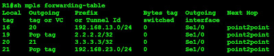
Observe the prefix 3.3.3.3, when R1 and R3 where directly connected before I shut down the link, the Outgoing tag or VC is Pop tag. This means that if R1 receives a packet destined for R3, it "pops" or removes the label and doesn't swap any label because in the LIB of R3, 3.3.3.3 has an implicit-null. After the link has been shut down, the Outgoing tag or VC now is 21. This literally means that R1 must swap a label of 21 to packets destined for 3.3.3.3. R2 in its LIB has 21 for 3.3.3.3. R2 to R3, should never be labeled because 3.3.3.3 originates from R3. Let's check the traceroute below for more proof.


R1#traceroute 3.3.3.3

Type escape sequence to abort.
Tracing the route to 3.3.3.3

1 192.168.12.2 [MPLS: Label 21 Exp 0] 88 msec 56 msec 60 msec
2 192.168.23.3 140 msec 76 msec *


The first hop is from R1 to R2. You can see clearly that it labeled 21. The 2nd hop did not display any labels.

Verifying and Configuring Label Range

A simple command to verify the label assignment range is "show mpls label range". The range of labels can also be set to your liking by using "mpls label range minrange maxrange" command.


R1#show mpls label range
Downstream Generic label region: Min/Max label: 16/100000
R1(config)#mpls label ?
protocol Set platform default label distribution protocol
range Label range

R1(config)#mpls label range ?
<16-1048575> Minimum label value

R1(config)#mpls label range 100 500000 static 50 70
% Label range changes will take effect at the next reload.


In the example above, we set the range to 100 minimum and 500000 for the maximum. I saved the config and restarted the router. The changes reflect right away when R1 fully restarted. It's local bindings now start from 100.


R1#sh mpls ldp bind
tib entry: 1.1.1.1/32, rev 4
local binding: tag: imp-null
remote binding: tsr: 2.2.2.2:0, tag: 19
tib entry: 2.2.2.2/32, rev 6
local binding: tag: 100
remote binding: tsr: 2.2.2.2:0, tag: imp-null
tib entry: 3.3.3.3/32, rev 8
local binding: tag: 101
remote binding: tsr: 2.2.2.2:0, tag: 21
tib entry: 192.168.12.0/24, rev 2
local binding: tag: imp-null
remote binding: tsr: 2.2.2.2:0, tag: imp-null
tib entry: 192.168.23.0/24, rev 10
local binding: tag: 102
remote binding: tsr: 2.2.2.2:0, tag: imp-null


MPLS Static Bindings

Using the range we configured about for the static bindings, lets configure 3.3.3.3 and statically assign a label of 65.


R1#sh mpls ldp binding
tib entry: 1.1.1.1/32, rev 4
local binding: tag: imp-null
remote binding: tsr: 2.2.2.2:0, tag: 19
tib entry: 2.2.2.2/32, rev 6
local binding: tag: 100
remote binding: tsr: 2.2.2.2:0, tag: imp-null
tib entry: 3.3.3.3/32, rev 12
local binding: tag: 65

------truncated---------------


So that concludes the MPLS Basics. Cheers!

Network Statements Shortcut for the Lazy

Sitting here reading blogs of famous CCIE's, I suddenly became sleepy. Tried some of the labs with lots of interfaces per device and I kinda feel lazy typing the network commands. So I did some of the shortcuts as I may say. I'm the kind of person who always looks for more effective and easier ways to accomplish something the right way. That's why im a fan of command aliases in Cisco routers.:) I'm not sure if this is the right way but it works for me when I'm lazy typing.

Here goes a simple solution to advertise all interfaces in a routing protocol. In this example I am using OSPF.


R1(config)#router ospf 1
R1(config-router)#network 0.0.0.0 0.0.0.0 area 0

R2(config)#router ospf 1
R2(config-router)#network 0.0.0.0 255.255.255.255 area 0


These network statements mean to match and advertise any ip segment originating from the router. It seems that using the wildcard mask 255.255.255.255 works also but I prefer the wildcard of 0.0.0.0 because its a lot easier to type. :)

This shortcut works effectively if you are doing your personal lab and at one point became lazy such as me. If you have interfaces that you want to advertise to a certain area, you can always add the network command and presto it will be in a new area. Enjoy but don't stay lazy!


Using Dynamips as Internet Router

Finally my first technical post! :) Dynamips as we know it has been instrumental to assist Cisco cert pursuers to understand and learn more about the configuration of the device. Ever since its inception it has garnered much respect and appreciation from all those who have used the software. It has evolved even to a GUI type application which is called GNS3. I myself, is a big fan of dynamips and using it for my labs. Dynamips saved me a lot of money and trouble of browsing ebay and purchasing Cisco equipment for sale. :)

Well enough talk about Dynamips. When I was in the middle of studying my ISCW, I was thinking of a way to use Dynamips as internet router. I tried a few things and with the help of others in the forums I finally made it work.

Disclaimer: The purpose of this is to demonstrate how to use PPPoE in a Cisco router and not for business purposes or to do away with real Cisco devices in favor of Dynamips.


To begin, of course you should have installed Dynamips and WinPcap and should have a running setup. Any latest IOS that is supported by Dynamips will do.

1. Create a loopback interface, if there is none. Hold CTRL and click both Loopback interface and the Local Area Network connection where your DSL modem is connected. Select Bridge Connections. A network bridge should appear. This serves like a virtual switch inside your computer connecting the loopback interface and the physical interface.

2. Restart your computer to utilize the full functionality of the network bridge. This would also allow you to see the NIO value of the network bridge in dynamips Network Device List tool.

3. Click on the icon Network Device List usually found on your desktop and look for the network Bridge NIO value.

4. Open your .net file and map the NIO value to the interface you intended to connect to the modem logically. Check the .net file I made below. I made autostart = true to speed things up once I open the .net file.


autostart = true
ghostios = true
sparsemem = true
# Dynamips internet router

[localhost]

[[7200]]
image = \Program Files\Dynamips\images\c7200-jk9o3s-mz.124-7a.bin
# On Linux / Unix use forward slashes:
# image = /opt/7200-images/c7200-jk9o3s-mz.124-7a.image
npe = npe-400
ram = 160

[[ROUTER R1]]
fa1/0 = NIO_gen_eth:\Device\NPF_{888833F9-9A11-478C-9859-1A8051CAC4AC}

Fa1/0 will serve as the connection to the modem and also the inside interface of the NAT configuration later on.

Go to Network Connections and right click on the Network Bridge and click Properties. Go to Internet Protocol and assign an Ip address on the same subnet as your modem. I used 192.168.1.100. Default gateway is 192.168.1.2 which would be the ip address of your dynamips fa1/0 interface.

5. Access your modem by its default management ip address by typing it on your web browser. Make sure that the operational mode is set to Bridge Mode and not PPPoE.

6. Start Dynamips and launch your .net file. Don't forget to get the idlepc values by typing idlepc get R1 after the Router> prompt appears. Select the appropriate idlepc value, usually the one with the * and save idlepc value using idlepc save R1.

7. Now lets start configuring the router! In this setup Fa1/0 serves as the logical connection to the modem and also the inside interface. So we have to configure the ip address on the same subnet as the modem. In my example, I am using the default (duh!) 192.168.1.1 for my modem, so I'll configure my Fa1/0 as 192.168.1.2.

Enable PPPoE on the interface and map it to a dial pool number. Dial pool number is used to map the physical interface with the dialer interface.


R1#config t
R1(config)#int fa1/0
R1(config-if)# ip address 192.168.1.2 255.255.255.0
R1(config-if)# no shut
R1(config-if)#pppoe enable
R1(config-if)#pppoe-client dial-pool-number 1

8. Create and configure a dialer interface. This will act as your pppoe dialer, like what you have in your Windows pc. The ip address must be set to negotiated for IPCP to provide it an ip address. You can only put a specific ip address here if you have bought a static ip from your ISP.


R1(config)#int dialer0
R1(config-if)#ip address negotiated
R1(config-if)#encapsulation ppp
R1(config-if)#dialer pool 1
R1(config-if)#ip mtu 1492

A dialer for DSL is incomplete without user credentials, therefore we should declare in the configuration what those are. I used both chap and pap because I don't know what my ISP is using. :)


R1(config)#ppp chap hostname pete
R1(config)#ppp chap password cisco
R1(config)#ppp pap sent-username pete password cisco

Right after this configuration it should work now. A Virtual Access interface Vi1 will be created on your router. You will see an ip address assigned to your Dialer interface. Good but we are not done yet!

9. Specify the default route. This should be pointing to the dialer interface.


R1(config)#ip route 0.0.0.0 0.0.0.0 dialer0

10. Never forget that we are using the internet and using private IP on our LAN so NATing is needed. Lets configure NATing as our last and final step. First specify an access list of what is to be NATed. Use a standard or extended, doesn't matter anyway.


R1(config)#access-list 100 permit ip 192.168.1.0 0.0.0.255 any

Specify the inside and outside interfaces.


R1(config)#int fa1/0
R1(config-if)#ip nat inside
R1(config)#int dialer0
R1(config-if)#ip nat outside

Declare which will be natted to which. In our case we will NAT the fa1/0 to whatever the ip address of Dialer0 is


R1(config)#ip nat inside source list 100 interface dialer0 overload

11. Find our your ISP's DNS servers and configure it on the router.


R1(config)# ip name-server 203.112.11.5
R1(config)# ip name-server 203.112.11.6

12. Test by browsing to the internet. Do a show ip nat translations and check if you are seeing ip address translations. This should work by now

Now you have a dynamips internet router working, don't be afraid to try several things. If you have a friend who uses this as well, try to create a Site to Site VPN. If you want to try FW, try it with an IOS with FW service. AutoQos is a good thing to try too. Enjoy!!!

Finally A CCNP!

It has been almost 2 years since I became a CCNA. I took and passed the exam May 2007 and waited for more than 1 year to begin my CCNP quest. My reason of not being able to take the exams was not having enough money to pay them. My CCNA paved a way for me to get a job in a company that encourages its employees to go for certifications and paying for them. The opportunities of being a CCNA are huge, how much more now that I got the CCNP.

Now the question is, what's next? Is everything over now I got this certification? Certainly not! I have been readings posts to find out what is the best field to study in preparation for CCIE and I found out that getting a CCDP and other professional Cisco certs are good ways to prepare for CCIE R&S. My level of excitement did not go down when I got my CCNP but I am rather excited to pursue more and learn more. The more I learn, the more I know how much I don't know. Makes sense? :)

Now as promised, I will be posting some of the labs I have tried using dynamips and practical tips to be used in the enterprise environment. Even if nobody reads this blog, this will serve as my personal reference once I forget about something. Cheers!

Certifications

Certifications

The Dreamer

A fun loving person who enjoys learning new things. Currently working as a Network Engineer supporting the global network of a Fortune 500 company. This blog serves as my notes for the labs I created for my CCIE journey. I can guarantee there are errors in my posts. If you spot them, please let me know.

Join my Facebook Page I WANT TO BE A CCIE

Donate to the Cause

My aim is to create materials for free and possibly a free lab. If you wish to help out, please send any amount. Thanks.

Join my Bandwagon

Blogs that I Read