Q: What are the 4 categories of BGP Attributes?
Highlight after < for the answer.
A: < 1) Well-known Mandatory 2) Well-known Discretionary 3) Optional Transitive 4) Optional Non-transitive
For more information on this visit this page:
http://www.brainbuzz.com/articles/files/border-gateway-protocol-a-982003-1304.asp

IPSEC VPN Configuration
IPSEC VPN's have revolutionized the networking world. It is usually used over the unsecured network called "the Internet". It's a way to ensure secure transfer of data over the internet and used for site to site connections and telecommuters who need remote access from anywhere to the corporate Intranet or for remote branch offices that only have internet connection. We have a basic diagram below and lets configure a Site to Site IPSEC VPN. We will focus more on configuration not on the nitty gritty details of the protocols and the process of VPN creation.
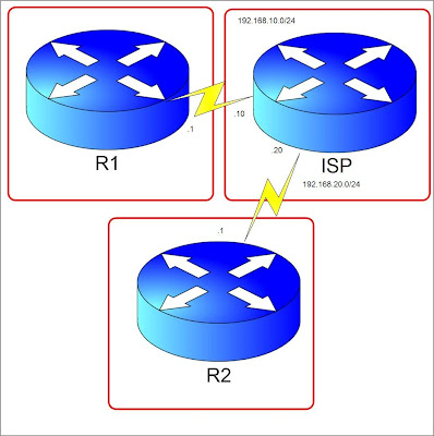
Let's pretend ISP is the Internet Cloud. We have R1 and R2 connected through an internet leased line to their ISP's. Lets say R2 has a server 2.2.2.2 which R1 needs to access from 1.1.1.1 in its network. (1.1.1.1 and 2.2.2.2 are just loopback addresses in R1 and R2 respectively) We will build a VPN tunnel allowing 1.1.1.1 to access 2.2.2.2 and vice versa. Steps are numbered but not necessarily the standard way but a more favorable way of configuring.
1. Create an access-list on both R1 and R2. This will indicate the "interesting traffic". This means that anything that matches the ACL applied to the tunnel configuration will pass through the tunnel instead of exiting the interface facing the internet.
Notice that the ACL's mirror each other.
2. Configure an ISAKMP key. This key will be used to generate more keys for VPN tunnel creation and must match between the peers.
The ip address at the end of the command is the IP address of the peer router.
3. Create an ISAKMP policy. The policy components like hashing, authentication, Diffie-Helman group, and lifetime must match. You can configure many different policies and the routers will check the ISAKMP policy until it finds a match of its own. It is checked sequentially by using policy sequence numbers. ISAKMP negotiation is also called Phase 1.
4. Configure Phase 2 which are IPSEC parameters.
Configure a crypto map.
5. Apply the Crypto map to the outgoing interface.
6. Make sure you have a route towards the peer vpn router public ip. In our case lets create a default route.
7. Finally lets test the connection. The tunnel won't come up until there is interesting traffic passing through the tunnel. Any traffic that will hit the access-list we matched in the crypto-map will trigger the tunnel negotiation. In our case lets ping 2.2.2.2 from R1 sourcing from the Loopback interface 1.1.1.1. In the ISP router, I have configured a route for the 2 loopback addresses.
To verify if the tunnel is up and running, lets use the "show crypto isakmp sa" to check Phase 1 status.
QM_IDLE means that the tunnel is up. If the state is not that, that means that there is a problem.
"Show crypto ipsec sa" displays Phase 2 information which includes the number of packets that used the tunnel and the source and destination IP. Thats it for the configuration. For more detailed information on the VPN negotiation process visit this link. Cheers

Let's pretend ISP is the Internet Cloud. We have R1 and R2 connected through an internet leased line to their ISP's. Lets say R2 has a server 2.2.2.2 which R1 needs to access from 1.1.1.1 in its network. (1.1.1.1 and 2.2.2.2 are just loopback addresses in R1 and R2 respectively) We will build a VPN tunnel allowing 1.1.1.1 to access 2.2.2.2 and vice versa. Steps are numbered but not necessarily the standard way but a more favorable way of configuring.
1. Create an access-list on both R1 and R2. This will indicate the "interesting traffic". This means that anything that matches the ACL applied to the tunnel configuration will pass through the tunnel instead of exiting the interface facing the internet.
R1(config)#access-list 100 permit ip host 1.1.1.1 host 2.2.2.2
R2(config)#access-list 100 permit ip host 2.2.2.2 host 1.1.1.1
Notice that the ACL's mirror each other.
2. Configure an ISAKMP key. This key will be used to generate more keys for VPN tunnel creation and must match between the peers.
R1(config)#crypto isakmp key 0 myvpnrouter address 192.168.20.1
R2(config)#crypto isakmp key 0 myvpnrouter address 192.168.10.1
The ip address at the end of the command is the IP address of the peer router.
3. Create an ISAKMP policy. The policy components like hashing, authentication, Diffie-Helman group, and lifetime must match. You can configure many different policies and the routers will check the ISAKMP policy until it finds a match of its own. It is checked sequentially by using policy sequence numbers. ISAKMP negotiation is also called Phase 1.
R1(config-isakmp)#crypto isakmp policy 10
R1(config-isakmp)#group 2
R1(config-isakmp)#hash md5
R1(config-isakmp)#lifetime 28800
R1(config-isakmp)#encryption aes
R1(config-isakmp)#authentication pre-share

R2(config-isakmp)#crypto isakmp policy 10
R2(config-isakmp)#group 2
R2(config-isakmp)#hash md5
R2(config-isakmp)#lifetime 28800
R2(config-isakmp)#encryption aes
R2(config-isakmp)#authentication pre-share
4. Configure Phase 2 which are IPSEC parameters.
R1(config)#crypto ipsec transform-set TRANSFORMERS esp-3des esp-sha-hmac
R1(config)#crypto ipsec security-association lifetime seconds 28800
R2(config)#crypto ipsec transform-set TRANSFORMERS esp-3des esp-sha-hmac
R2(config)#crypto ipsec security-association lifetime seconds 28800
Configure a crypto map.
R1(config)#crypto map MYMAP 10 ipsec-isakmp
% NOTE: This new crypto map will remain disabled until a peer
        and a valid access list have been configured.
R1(config-crypto-map)#match address 100
R1(config-crypto-map)#description to R2
R1(config-crypto-map)#set transform-set TRANSFORMERS
R1(config-crypto-map)#set peer 192.168.20.1
R1(config-crypto-map)#set security-association lifetime seconds 28800

R2(config)#crypto map MYMAP 10 ipsec-isakmp
 % NOTE: This new crypto map will remain disabled until a peer
         and a valid access list have been configured.
R2(config-crypto-map)#match address 100
R2(config-crypto-map)#description to R1
R2(config-crypto-map)#set transform-set TRANSFORMERS
R2(config-crypto-map)#set peer 192.168.10.1
R2(config-crypto-map)#set security-association lifetime seconds 28800
5. Apply the Crypto map to the outgoing interface.
R1(config)#int se1/1
R1(config-if)#crypto map MYMAP
R1(config-if)#
*Jul 11 13:05:47.007: %CRYPTO-6-ISAKMP_ON_OFF: ISAKMP is ON

R2(config)#int se1/2
R2(config-if)#crypto map MYMAP
R2(config-if)#
*Jul 11 13:05:47.007: %CRYPTO-6-ISAKMP_ON_OFF: ISAKMP is ON
6. Make sure you have a route towards the peer vpn router public ip. In our case lets create a default route.
R1(config)#ip route 0.0.0.0 0.0.0.0 192.168.10.10 name To_R2
R2(config)#ip route 0.0.0.0 0.0.0.0 192.168.20.20 name To_R1
7. Finally lets test the connection. The tunnel won't come up until there is interesting traffic passing through the tunnel. Any traffic that will hit the access-list we matched in the crypto-map will trigger the tunnel negotiation. In our case lets ping 2.2.2.2 from R1 sourcing from the Loopback interface 1.1.1.1. In the ISP router, I have configured a route for the 2 loopback addresses.
ISP(config)#ip route 2.2.2.2 255.255.255.255 192.168.20.1
ISP(config)#ip route 1.1.1.1 255.255.255.255 192.168.10.1

R1#ping 2.2.2.2 source 1.1.1.1

Type escape sequence to abort.
Sending 5, 100-byte ICMP Echos to 2.2.2.2, timeout is 2 seconds:
Packet sent with a source address of 1.1.1.1
!!!!!
To verify if the tunnel is up and running, lets use the "show crypto isakmp sa" to check Phase 1 status.
R1#sh cry isakmp sa
dst             src             state          conn-id slot status
192.168.20.1    192.168.10.1    QM_IDLE              1    0 ACTIVE
QM_IDLE means that the tunnel is up. If the state is not that, that means that there is a problem.
"Show crypto ipsec sa" displays Phase 2 information which includes the number of packets that used the tunnel and the source and destination IP. Thats it for the configuration. For more detailed information on the VPN negotiation process visit this link. Cheers
Question of the Day: July 11, 2009
Q: What is a virtual link?
Highlight after < for the answer.
A: < All areas in an OSPF autonomous system must be physically connected to the backbone area (area 0). In some cases where this physical connection is not possible, you can use a virtual link to connect to the backbone through a non-backbone area. As mentioned above, you can also use virtual links to connect two parts of a partitioned backbone through a non-backbone area. The area through which you configure the virtual link, known as a transit area, must have full routing information. The transit area cannot be a stub area.
For more information on virtual-links visit this page:
http://www.cisco.com/en/US/tech/tk365/technologies_configuration_example09186a00801ec9ee.shtml
Highlight after < for the answer.
A: < All areas in an OSPF autonomous system must be physically connected to the backbone area (area 0). In some cases where this physical connection is not possible, you can use a virtual link to connect to the backbone through a non-backbone area. As mentioned above, you can also use virtual links to connect two parts of a partitioned backbone through a non-backbone area. The area through which you configure the virtual link, known as a transit area, must have full routing information. The transit area cannot be a stub area.
For more information on virtual-links visit this page:
http://www.cisco.com/en/US/tech/tk365/technologies_configuration_example09186a00801ec9ee.shtml
Question of the Day Portion
Its been a while since I last posted an entry. I have been doing some reading and I feel that for the mastery of the topics, a question of the day portion would be very nice. CCIE Pursuit blog shows some excellent Question of the day portion which I think would be good for my blog. All credit goes to CCIE Pursuit blog for this idea! From here own, I'll start the question of the day.
VRF Basics
When we hear about VRF, its almost synonymous to MPLS VPN. Virtual Routing and Forwarding is commonly used by Service Providers to provide services within an MPLS cloud with multiple customers. The most interesting feature of this is that, VRF allows creation of multiple routing tables within a single router. This means that overlapping use of IP addresses from different customers is possible. Some enterprises use VRF to seggrate their services like VOIP, wireless, geographical location and other varieties. Through the network setup below, we will see how to configure VRF and check if its really possible for duplicate ip addresses. We have 3 customers in the figure connected to a Provider Edge router. We will name the VRF's Blue, Red and Yellow. Click image for a bigger view.

Now let's configure RD's on the PE router.
Basically the "rd" command is in the format ASN:nn or IP-address:nn. The VRF names and rd values are actually locally significant which means that it doesn't matter what name you create. What really matters is the "route target" value because this is what you will import or export. More about this on the next blog entry.
Now we have created VRF's, lets configure interfaces and apply the VRF's to the interfaces.
If you notice above all interfaces have the same ip address which is 1.1.1.1. Normally without VRF, the router will give a warning message that overlapping ip addresses are not allowed. The command "ip vrf forwarding" will add the vrf to a specific interface.
Let's configure the other routers Blue, Red and Yellow with 1.1.1.2/30 on their FastEthernet0/0 interfaces. Lets ping 1.1.1.1 from the routers.
It's good! We have ip reachability to PE from the CE routers. Now, from PE point of view, how will PE know which one to ping if we use 1.1.1.2 since all Blue, Red and Yellow routers use the same ip? This can be accomplished using the "ping vrf " command. See below.
Now, we have proven that duplicate IP addresses is possible using VRF. Be reminded that VRF's are usually and by standard configured on PE routers. CE routers normally don't make use of VRF's but there are always exceptions. Next entries will focus on importing Route Targets and using IGP's and BGP on a MPLS VPN setup. Cheers.

Now let's configure RD's on the PE router.
Router(config)#host PE
PE(config)#ip vrf blue
PE(config-vrf)#rd 1:1
PE(config-vrf)#ip vrf red
PE(config-vrf)#rd 2:2
PE(config-vrf)#ip vrf yellow
PE(config-vrf)#rd 3:3
Basically the "rd" command is in the format ASN:nn or IP-address:nn. The VRF names and rd values are actually locally significant which means that it doesn't matter what name you create. What really matters is the "route target" value because this is what you will import or export. More about this on the next blog entry.
Now we have created VRF's, lets configure interfaces and apply the VRF's to the interfaces.
PE(config)#int fa0/0.2
PE(config-subif)#encapsulation dot1q 2
PE(config-subif)#ip vrf forwarding blue
PE(config-subif)#ip address 1.1.1.1 255.255.255.252
PE(config-subif)#int fa0/0.3
PE(config-subif)#encapsulation dot1q 3
PE(config-subif)#ip vrf forwarding red
PE(config-subif)#ip address 1.1.1.1 255.255.255.252
PE(config-subif)#int fa0/0.4
PE(config-subif)#encapsulation dot1q 4
PE(config-subif)#ip vrf forwarding yellow
PE(config-subif)#ip address 1.1.1.1 255.255.255.252
If you notice above all interfaces have the same ip address which is 1.1.1.1. Normally without VRF, the router will give a warning message that overlapping ip addresses are not allowed. The command "ip vrf forwarding
Let's configure the other routers Blue, Red and Yellow with 1.1.1.2/30 on their FastEthernet0/0 interfaces. Lets ping 1.1.1.1 from the routers.
Blue#ping 1.1.1.1

Type escape sequence to abort.
Sending 5, 100-byte ICMP Echos to 1.1.1.1, timeout is 2 seconds:
!!!!!
Success rate is 100 percent (5/5), round-trip min/avg/max = 8/35/80 ms

Red#ping 1.1.1.1

Type escape sequence to abort.
Sending 5, 100-byte ICMP Echos to 1.1.1.1, timeout is 2 seconds:
!!!!!
Success rate is 100 percent (5/5), round-trip min/avg/max = 8/48/156 ms

Yellow#ping 1.1.1.1

Type escape sequence to abort.
Sending 5, 100-byte ICMP Echos to 1.1.1.1, timeout is 2 seconds:
!!!!!
Success rate is 100 percent (5/5), round-trip min/avg/max = 8/60/136 ms
It's good! We have ip reachability to PE from the CE routers. Now, from PE point of view, how will PE know which one to ping if we use 1.1.1.2 since all Blue, Red and Yellow routers use the same ip? This can be accomplished using the "ping vrf
PE#ping vrf blue 1.1.1.2

Type escape sequence to abort.
Sending 5, 100-byte ICMP Echos to 1.1.1.2, timeout is 2 seconds:
!!!!!
Success rate is 100 percent (5/5), round-trip min/avg/max = 4/28/68 ms
PE#ping vrf red 1.1.1.2

Type escape sequence to abort.
Sending 5, 100-byte ICMP Echos to 1.1.1.2, timeout is 2 seconds:
!!!!!
Success rate is 100 percent (5/5), round-trip min/avg/max = 4/28/88 ms
PE#ping vrf yellow 1.1.1.2

Type escape sequence to abort.
Sending 5, 100-byte ICMP Echos to 1.1.1.2, timeout is 2 seconds:
!!!!!
Success rate is 100 percent (5/5), round-trip min/avg/max = 8/31/68 ms
Now, we have proven that duplicate IP addresses is possible using VRF. Be reminded that VRF's are usually and by standard configured on PE routers. CE routers normally don't make use of VRF's but there are always exceptions. Next entries will focus on importing Route Targets and using IGP's and BGP on a MPLS VPN setup. Cheers.
Simple TCL Ping Script
Doing ping tests for lots of IP addresses can be tiring since you can't paste all the ping commands at the same time. You have to do it one at a time. All you need is Patience or you can opt for a TCL scripting language which is already available in Cisco IOS 12.2(25). At first, I thought you need to learn TCL scripting to be a CCIE but nah! :) All you need is the basics and if you are interested learning more about TCL you can click here. To access the tcl command line in Cisco router issue the "tclsh" command. For the ping script just modify the ip addresses what is shown below and it should be good.
The word "address" here is just a variable, you can substitute this with anything you want. Now lets try applying this to the Cisco router.
How cool is that!!! This script can be useful when you are doing your CCIE lab exams as they say, when you want to verify that every subnet in your lab routers are reachable. You can try this in your own Dynamips lab. This should be safe to be done in the production routers but where I work, I doubt if this will be allowed by the company's IT policy. :P
foreach address {
1.1.1.1
2.2.2.2
3.3.3.3
4.4.4.4
5.5.5.5
6.6.6.6
} { puts [ exec "ping $address" ] }
The word "address" here is just a variable, you can substitute this with anything you want. Now lets try applying this to the Cisco router.
R0#tclsh
R0(tcl)#foreach address {
+>(tcl)#1.1.1.1
+>(tcl)#2.2.2.2
+>(tcl)#3.3.3.3
+>(tcl)#4.4.4.4
+>(tcl)#5.5.5.5
+>(tcl)#6.6.6.6
+>(tcl)#} { puts [ exec "ping $address" ] }

Type escape sequence to abort.
Sending 5, 100-byte ICMP Echos to 1.1.1.1, timeout is 2 seconds:
!!!!!
Success rate is 100 percent (5/5), round-trip min/avg/max = 4/44/100 ms

Type escape sequence to abort.
Sending 5, 100-byte ICMP Echos to 2.2.2.2, timeout is 2 seconds:
!!!!!
Success rate is 100 percent (5/5), round-trip min/avg/max = 8/27/56 ms

Type escape sequence to abort.
Sending 5, 100-byte ICMP Echos to 3.3.3.3, timeout is 2 seconds:
!!!!!
Success rate is 100 percent (5/5), round-trip min/avg/max = 1/26/96 ms

Type escape sequence to abort.
Sending 5, 100-byte ICMP Echos to 4.4.4.4, timeout is 2 seconds:
!!!!!
Success rate is 100 percent (5/5), round-trip min/avg/max = 4/27/52 ms

Type escape sequence to abort.
Sending 5, 100-byte ICMP Echos to 5.5.5.5, timeout is 2 seconds:
!!!!!
Success rate is 100 percent (5/5), round-trip min/avg/max = 4/27/96 ms

Type escape sequence to abort.
Sending 5, 100-byte ICMP Echos to 6.6.6.6, timeout is 2 seconds:
!!!!!
Success rate is 100 percent (5/5), round-trip min/avg/max = 4/32/84 ms
How cool is that!!! This script can be useful when you are doing your CCIE lab exams as they say, when you want to verify that every subnet in your lab routers are reachable. You can try this in your own Dynamips lab. This should be safe to be done in the production routers but where I work, I doubt if this will be allowed by the company's IT policy. :P
BGP Local-AS
When configuring BGP, we usually use the "remote-as" command to specify the AS of the neighbor specified. The purpose of the "local-as" command is to spoof the neighbor router by advertising a different AS other than the real AS of the originating router. This command is very useful whenever there is an ISP merger, when one ISP purchases another. Let's say ISP1 purchases ISP 2 and wants it to belong to AS 12345. The customers of ISP2's routers should need to configure the new "remote-as" on their end because ISP2 will now be on AS12345. As a temporary solution, "local-as" command can be configured on the ISPs's router and still have a BGP adjancency without any changes on the customer side. To see how local-as functions, let's take the diagram below as an example.

Scenario: R2 used to belong to AS 250 and now is on AS 200.
First, let see what happens in the router is there is a "remote-as" mismatch on the neighbors.
This is because R1 is configured as "neighbor 192.168.12.2 remote-as 250" but R2 now belongs to AS 200. Lets configure "local-as" in R2.
Now, adjacency is up! R2 "spoofed" its AS by sending AS 250 instead of AS 200. There is an option you can add to the local-as command. The "no-prepend" command. Before adding the option lets check "show ip bgp" output.
We notice that in the AS path, we can see AS 250. Lets check the routers after adding the "no-prepend" option.
R1 is not affected by the command, but R2 and R3 are. We can now see, that the AS 250 path is no longer included in the AS path. That's the purpose of the "no-prepend" command option, to hide that local-as configured from the other ebgp peers/ There is a "sub-option" however, for the "no-prepend" commands and that is the "replace-as" command. Lets see what it does.
This command somehow affects R1 only, and what it does is it replaces AS 200 with AS 250 on the AS path.

Scenario: R2 used to belong to AS 250 and now is on AS 200.
First, let see what happens in the router is there is a "remote-as" mismatch on the neighbors.
R2#
*May 10 15:33:38.983: %BGP-3-NOTIFICATION: received from neighbor 192.168.12.1 2
/2 (peer in wrong AS) 2 bytes 00C8
This is because R1 is configured as "neighbor 192.168.12.2 remote-as 250" but R2 now belongs to AS 200. Lets configure "local-as" in R2.
R2#config t
Enter configuration commands, one per line. End with CNTL/Z.
R2(config)#router bgp 200
R2(config-router)#neighbor 192.168.12.1 local-as 250
*May 10 15:39:02.931: %BGP-5-ADJCHANGE: neighbor 192.168.12.1 Up neighbor 192.168.12.1
Now, adjacency is up! R2 "spoofed" its AS by sending AS 250 instead of AS 200. There is an option you can add to the local-as command. The "no-prepend" command. Before adding the option lets check "show ip bgp" output.
*May 10 16:29:49.119: %BGP-5-ADJCHANGE: neighbor 192.168.12.2 Up
R1#sh ip bgp
BGP table version is 55, local router ID is 11.11.11.11
Status codes: s suppressed, d damped, h history, * valid, > best, i - internal,
r RIB-failure, S Stale
Origin codes: i - IGP, e - EGP, ? - incomplete

Network Next Hop Metric LocPrf Weight Path
*> 1.1.1.1/32 0.0.0.0 0 32768 i
*> 2.2.2.2/32 192.168.12.2 0 0 250 200 i
*> 3.3.3.3/32 192.168.12.2 0 250 200 300 i
*> 11.11.11.11/32 0.0.0.0 0 32768 i
*> 22.22.22.22/32 192.168.12.2 0 0 250 200 i
*> 33.33.33.33/32 192.168.12.2 0 250 200 300 i

R2#sh ip bgp
BGP table version is 63, local router ID is 22.22.22.22
Status codes: s suppressed, d damped, h history, * valid, > best, i - internal,
r RIB-failure, S Stale
Origin codes: i - IGP, e - EGP, ? - incomplete

Network Next Hop Metric LocPrf Weight Path
*> 1.1.1.1/32 192.168.12.1 0 0 250 100 i
*> 2.2.2.2/32 0.0.0.0 0 32768 i
*> 3.3.3.3/32 192.168.23.3 0 0 300 i
*> 11.11.11.11/32 192.168.12.1 0 0 250 100 i
*> 22.22.22.22/32 0.0.0.0 0 32768 i
*> 33.33.33.33/32 192.168.23.3 0 0 300 i

R3#sh ip bgp
BGP table version is 35, local router ID is 33.33.33.33
Status codes: s suppressed, d damped, h history, * valid, > best, i - internal,
r RIB-failure, S Stale
Origin codes: i - IGP, e - EGP, ? - incomplete

Network Next Hop Metric LocPrf Weight Path
*> 1.1.1.1/32 192.168.23.2 0 200 250 100 i
*> 2.2.2.2/32 192.168.23.2 0 0 200 i
*> 3.3.3.3/32 0.0.0.0 0 32768 i
*> 11.11.11.11/32 192.168.23.2 0 200 250 100 i
*> 22.22.22.22/32 192.168.23.2 0 0 200 i
*> 33.33.33.33/32 0.0.0.0 0 32768 i
We notice that in the AS path, we can see AS 250. Lets check the routers after adding the "no-prepend" option.
R2(config-router)#neighbor 192.168.12.1 local-as 250 no-prepend
R1#sh ip bgp
BGP table version is 63, local router ID is 11.11.11.11
Status codes: s suppressed, d damped, h history, * valid, > best, i - internal,
r RIB-failure, S Stale
Origin codes: i - IGP, e - EGP, ? - incomplete

Network Next Hop Metric LocPrf Weight Path
*> 1.1.1.1/32 0.0.0.0 0 32768 i
*> 2.2.2.2/32 192.168.12.2 0 0 250 200 i
*> 3.3.3.3/32 192.168.12.2 0 250 200 300 i
*> 11.11.11.11/32 0.0.0.0 0 32768 i
*> 22.22.22.22/32 192.168.12.2 0 0 250 200 i
*> 33.33.33.33/32 192.168.12.2 0 250 200 300 i

R2#sh ip bgp
BGP table version is 79, local router ID is 22.22.22.22
Status codes: s suppressed, d damped, h history, * valid, > best, i - internal,
r RIB-failure, S Stale
Origin codes: i - IGP, e - EGP, ? - incomplete

Network Next Hop Metric LocPrf Weight Path
*> 1.1.1.1/32 192.168.12.1 0 0 100 i
*> 2.2.2.2/32 0.0.0.0 0 32768 i
*> 3.3.3.3/32 192.168.23.3 0 0 300 i
*> 11.11.11.11/32 192.168.12.1 0 0 100 i
*> 22.22.22.22/32 0.0.0.0 0 32768 i
*> 33.33.33.33/32 192.168.23.3 0 0 300 i

R3#sh ip bgp
BGP table version is 39, local router ID is 33.33.33.33
Status codes: s suppressed, d damped, h history, * valid, > best, i - internal,
r RIB-failure, S Stale
Origin codes: i - IGP, e - EGP, ? - incomplete

Network Next Hop Metric LocPrf Weight Path
*> 1.1.1.1/32 192.168.23.2 0 200 100 i
*> 2.2.2.2/32 192.168.23.2 0 0 200 i
*> 3.3.3.3/32 0.0.0.0 0 32768 i
*> 11.11.11.11/32 192.168.23.2 0 200 100 i
*> 22.22.22.22/32 192.168.23.2 0 0 200 i
*> 33.33.33.33/32 0.0.0.0 0 32768 i
R1 is not affected by the command, but R2 and R3 are. We can now see, that the AS 250 path is no longer included in the AS path. That's the purpose of the "no-prepend" command option, to hide that local-as configured from the other ebgp peers/ There is a "sub-option" however, for the "no-prepend" commands and that is the "replace-as" command. Lets see what it does.
R2(config-router)#neighbor 192.168.12.1 local-as 250 no-prepend replace-as

R1#sh ip bgp
BGP table version is 47, local router ID is 11.11.11.11
Status codes: s suppressed, d damped, h history, * valid, > best, i - internal,
r RIB-failure, S Stale
Origin codes: i - IGP, e - EGP, ? - incomplete

Network Next Hop Metric LocPrf Weight Path
*> 1.1.1.1/32 0.0.0.0 0 32768 i
*> 2.2.2.2/32 192.168.12.2 0 0 250 i
*> 3.3.3.3/32 192.168.12.2 0 250 300 i
*> 11.11.11.11/32 0.0.0.0 0 32768 i
*> 22.22.22.22/32 192.168.12.2 0 0 250 i
*> 33.33.33.33/32 192.168.12.2 0 250 300 i

R2#sh ip bgp
BGP table version is 71, local router ID is 22.22.22.22
Status codes: s suppressed, d damped, h history, * valid, > best, i - internal,
r RIB-failure, S Stale
Origin codes: i - IGP, e - EGP, ? - incomplete

Network Next Hop Metric LocPrf Weight Path
*> 1.1.1.1/32 192.168.12.1 0 0 100 i
*> 2.2.2.2/32 0.0.0.0 0 32768 i
*> 3.3.3.3/32 192.168.23.3 0 0 300 i
*> 11.11.11.11/32 192.168.12.1 0 0 100 i
*> 22.22.22.22/32 0.0.0.0 0 32768 i
*> 33.33.33.33/32 192.168.23.3 0 0 300 i

R3#sh ip bgp
BGP table version is 31, local router ID is 33.33.33.33
Status codes: s suppressed, d damped, h history, * valid, > best, i - internal,
r RIB-failure, S Stale
Origin codes: i - IGP, e - EGP, ? - incomplete

Network Next Hop Metric LocPrf Weight Path
*> 1.1.1.1/32 192.168.23.2 0 200 100 i
*> 2.2.2.2/32 192.168.23.2 0 0 200 i
*> 3.3.3.3/32 0.0.0.0 0 32768 i
*> 11.11.11.11/32 192.168.23.2 f0 200 100 i
*> 22.22.22.22/32 192.168.23.2 0 0 200 i
*> 33.33.33.33/32 0.0.0.0 0 32768 i
This command somehow affects R1 only, and what it does is it replaces AS 200 with AS 250 on the AS path.
Cisco Router as a DNS server
Not exactly like a DNS server that is hosted from a server and so on and so forth, the Cisco Router can act like a DNS server without the service stated above. It can even act as a proxy dns server, meaning forwarding the request to the upstream DNS server and cache the replies from the DNS server, so it can use the cache entries for other requesting hosts. We will only focus on the simple and practical configuration. I don't even know if this feature can be called a "DNS server" feature. :P If you have your own Dynamips Lab and has fixed ip addresses, it would be easier though to use hostnames when trying to ping devices. This can be achieved by the "ip host" command. It can be configured as the example below.
Let's do a ping test.
Well, R1 now resolves to 1.1.1.1. There you have it, makes life easier! :P
Router(config)#ip host R1 1.1.1.1
Router(config)#ip host R2 2.2.2.2
Router(config)#ip host R3 3.3.3.3
Router(config)#ip host R4 4.4.4.4
Let's do a ping test.
Router#ping R1

Type escape sequence to abort.
Sending 5, 100-byte ICMP Echos to 1.1.1.1, timeout is 2 seconds:
...
Well, R1 now resolves to 1.1.1.1. There you have it, makes life easier! :P
Using Aliases in Cisco Routers
Cisco has long, frequently used commands like our favorites "show ip interface brief", "show ip route" and the annoying "do show" commands while in the global configuration mode. If you want the easy way, the good news is there is an easy way. Using aliases will save you some keystrokes. Here's the way to configure aliases. We will create aliases for the commands above and also be able to use the "show" command on the global configuration mode. "show ip interface brief" will be assigned with the alias "sib", "show ip route" will be "sir" and "do show" will be "show".
Let's test if the alias commands really work.
Well it did! Lets check what we will see in IOS help.
Now we see the aliases we made and they have the preceeding asterisk before them. *s=show is the default alias in the router. Cool! Try other aliases in different modes, make your own aliases and just be creative!
Router(config)#alias exec sib show ip interface brief
Router(config)#alias exec sir show ip route
Router(config)#alias configure show do show
Let's test if the alias commands really work.
Router#sib
Interface                  IP-Address      OK? Method Status                Protocol
FastEthernet0/0            unassigned      YES unset  administratively down down

Router#sir
Codes: C - connected, S - static, R - RIP, M - mobile, B - BGP
  D - EIGRP, EX - EIGRP external, O - OSPF, IA - OSPF inter area
  N1 - OSPF NSSA external type 1, N2 - OSPF NSSA external type 2
  E1 - OSPF external type 1, E2 - OSPF external type 2
  i - IS-IS, su - IS-IS summary, L1 - IS-IS level-1, L2 - IS-IS level-2
  ia - IS-IS inter area, * - candidate default, U - per-user static route
  o - ODR, P - periodic downloaded static route

Gateway of last resort is not set

Router#config t
Enter configuration commands, one per line.  End with CNTL/Z.
Router(config)#show ip int brief
Interface                  IP-Address      OK? Method Status                Protocol

FastEthernet0/0            unassigned      YES unset  administratively down down
Well it did! Lets check what we will see in IOS help.
Router#s?
*s=show     *sib="show ip interface brief"  *sir="show ip route"  sdlc
send        set                             setup                 show
slip        snasw                           squeeze               ssh
start-chat  systat

Router#config t
Enter configuration commands, one per line.  End with CNTL/Z.
Router(config)#s?
*show="do show"  sap-priority-list  scheduler          scripting
secure           security           service            sgbp
signaling-class  sip-ua             sna                snasw
snmp             snmp-server        source-bridge      srcp
standby          state-machine      stun               su-mac
su-tag           subscriber         subscriber-policy  subscription
Now we see the aliases we made and they have the preceeding asterisk before them. *s=show is the default alias in the router. Cool! Try other aliases in different modes, make your own aliases and just be creative!
Using Parser View In Cisco Routers
What exactly is a parser view? In simple terms, its like creating user accounts with certain filtering of commands. Parser views can be used to customize which command are allowed for a certain user depending on their privileges. Its simple to create parser views but doing the command filtering takes a while to learn.
Let's make a parser view called "user". One requirement needed is to enable first the "root" view. The hierarchy is similar to Unix/Linux wherein there should be a root. Secondly AAA must be enabled and thirdly, there should be an enable secret configured on the router.
Now from the root view, this is where we create all other views and define the commands that can be included or excluded per view.
We can set a password for the parser view "user".
Great! Our parser view is done. Lets say, we exclude the reload command for this view. Pretty dangerous if someone not authorize will reload the router!
Lets dissect what the command above does. The word command is literally for the commands allowed. "Exec" is for the privilege exec mode since reload is done on the mode and "reload" is basically the command itself. We can see its the same hierarchy as configuration.
For testing, we will go to parser view and try reloading the router.
Cool! Now reload command doesn't work on that mode anymore. I have my online hopping server which I configured with parser view so my friends won't do any cpu or performance intensive commands in the routers.
The router's behavior regarding parser view is that it adds command opposite to the one you excluded. Lets say for example "commands exec exclude debug ip packet". Since this command is excluded the undebug part also should be excluded. The router automatically generated this command "commands exec exclude undebug ip packet".
There you have it. Enjoy and try configuring some parser views.
Let's make a parser view called "user". One requirement needed is to enable first the "root" view. The hierarchy is similar to Unix/Linux wherein there should be a root. Secondly AAA must be enabled and thirdly, there should be an enable secret configured on the router.
It would need to be in the privilege exec mode to access the root view.
Router#config t
Enter configuration commands, one per line.  End with CNTL/Z.
Router(config)#aaa new
Router(config)#aaa new-model
Router(config)#enable view root
Routerconfig)#enable secret cisco
Router#sh parser view
No view is active ! Currently in Privilege Level Context
Router#enable view root
Password:
*May  2 00:50:51.283: %PARSER-6-VIEW_SWITCH: successfully set to view 'root'.

Router#show parser view
Current view is 'root'
Now from the root view, this is where we create all other views and define the commands that can be included or excluded per view.
Router(config)#parser view user
Router(config-view)#
*May  2 00:52:54.999: %PARSER-6-VIEW_CREATED: view 'user' successfully created.
We can set a password for the parser view "user".
Router(config-view)#secret cisco
Great! Our parser view is done. Lets say, we exclude the reload command for this view. Pretty dangerous if someone not authorize will reload the router!
Router(config-view)#commands exec exclude reload
Lets dissect what the command above does. The word command is literally for the commands allowed. "Exec" is for the privilege exec mode since reload is done on the mode and "reload" is basically the command itself. We can see its the same hierarchy as configuration.
For testing, we will go to parser view and try reloading the router.
Router#enable view user
Password:
Router#reload
 ^
% Invalid input detected at '^' marker.
Cool! Now reload command doesn't work on that mode anymore. I have my online hopping server which I configured with parser view so my friends won't do any cpu or performance intensive commands in the routers.
commands configure exclude aaa
commands exec include all telnet
commands exec include all write
commands exec include all traceroute
commands exec include all ping
commands exec include all enable
commands exec include all configure
commands exec include all send
commands exec exclude reload
commands exec exclude undebug ip packet
commands exec include undebug ip
commands exec exclude undebug all
commands exec include all undebug
commands exec include all show
commands exec include all set
commands exec exclude debug ip packet
commands exec include debug ip
commands exec exclude debug all
commands exec include all debug
commands configure exclude interface FastEthernet0/0
The router's behavior regarding parser view is that it adds command opposite to the one you excluded. Lets say for example "commands exec exclude debug ip packet". Since this command is excluded the undebug part also should be excluded. The router automatically generated this command "commands exec exclude undebug ip packet".
There you have it. Enjoy and try configuring some parser views.
Certifications

Blogs that I Read
-
-
-
-
IPv6 radius accounting is still a mess - Since the beginning of putting IPv6 into production BRAS/BNG (almost 3 years ago), we were facing the following issue: radius accounting records were missi...12 years ago
-
Internetwork Expert Volume IV (Troubleshooting) Workbook Review: Part 3 - Once you get the initial configurations loaded you’re ready to begin the lab. This is when the “fun” begins. Those of us who are used to starting labs wi...17 years ago
-
-
Cavani Authorize Central Approached Atletico Madrid Squad - Atletico Madrid Squad – PSG striker Edinson Cavani, incredulously, if he is a similar player Luis Suarez, though they are both from Uruguay. CAVANI will be...9 years ago
-
Network Engineer Jobs - So you want to work for Google as Network Engineer? Check out one of the job ads here. I pasted the screenshot below just in case the ad is removed once...9 years ago
-
Interested in Microsoft Azure? Tune into James Rudley’s Newest Course - Get ready to explore the different methods of automating technical and business challenges with Azure in James Rudley’s new course; Automation With Microso...7 years ago
-
Worth Reading: An Interactive Introduction to the STP - I can’t even start imagining how much time Vincent Bernat spent creating his interactive introduction to the spanning tree protocol (starting with STP im...1 week ago
-
Clearing the fog around open switching terminology - The networking industry is making a decisive move toward open switches. Much of the media's attention is on mega-scale operators' do-it-yourself switche...11 years ago
-
-
A Short Summary of Planes - A Short Summary of Planes (the network kind) When the CCDE program was first developed, Cisco conveniently broke down the included technologies into five...8 years ago
-
Book Review: Model-Driven DevOps - Earlier this month at Cisco Live in Las Vegas, I attended a presentation by Steven Carter and Jason King titled *Model-Driven DevOps: The Enterprise Auto...3 years ago
-
Data Center Study - Notes 01 - - reverse proxy caching - the user of loadbalancers for server health monitoring - the need for jumbo frames - the need for NIC features such as interrupt co...13 years ago
-
-
I’m Back - Well hello blog world. Yes it’s been a while since I last posted an update. I meant to update sooner but because I haven’t logged on to WordPress in such a...13 years ago
-
Integrating the Nexus 1000v VSM with vCenter - This is a follow-up to my previous post regarding the Nexus 1000v. Now that I help set the stage for what the Nexus 1000v really is, we can start looking a...17 years ago
-


Subscribe


 Posts
All Comments
Posts
All Comments
