Showing posts with label CCSP. Show all posts

Firewall Security-Level

This is my first Security Post regarding Cisco PIX/ASA firewalls. To begin with, what is a firewall? Literally, in the real world, a firewall as part of a building, is used to you guessed it: protect the building from fire. :) The same applies in the networking world. A firewall is a device that prevents unauthorized access and permits authorized access to a network. A firewall may function for packet filtering, proxy server and stateful packet filtering. Cisco PIX/ASA devices function as stateful packet filtering devices, which builds a stateful connection table to verify the connections.

A firewall prevents access from the untrusted network to the trusted network. An interface of the firewall may belong to the untrusted or the trusted. The interface that belongs to the trusted network is often called the inside interface and the untrusted one is the outside interface. Security-levels from 0-100 indicates the level of trust for an interface. The higher the number the more trusted the interface. The rule in security-level is that a higher security level can have access to a lower security level, the lower security level doesn't have access to a higher security level and is blocked by default. Interfaces with the same security levels are blocked as well.

Let's configure interfaces and lets see how security-levels are applied automatically and manually. I am using a PIX firewall.

First lets configure an outside interface.


petesfirewall(config)# interface ethernet0
petesfirewall(config-if)# nameif outside
INFO: Security level for "outside" set to 0 by default.

The "nameif" command is basically used to name an interface. Very obvious isn't it?:) Notice that once we named the interface "outside", Cisco automatically set the security-level to 0 meaning its untrusted. Next we configure an inside interface.


petesfirewall(config-if)# interface ethernet1
petesfirewall(config-if)# nameif inside
INFO: Security level for "inside" set to 100 by default.

The PIX now configures the security level by 100 which means its a trusted interface. For this reason, traffic from ethernet1 to ethernet0 is permitted by default but traffic from ethernet0 to ethernet1 is not. This is where inbound access-list comes in to allow traffic from an untrusted interface to a trusted one.

Let us now configure an interface named "webservers". You can use any name you like by the way. Let's give it a security-level of 60.


petesfirewall(config-if)# interface ethernet2
petesfirewall(config-if)# nameif webservers
INFO: Security level for "webservers" set to 0 by default.
petesfirewall(config-if)# security-level 60

Notice that any interface name other than "inside" is automatically given a 0 security-level value. The "security-level" command is used to specify manually a security level to an interface. Ethernet2 by default can access Ethernet0 but can't access Ethernet1, because the latter has a higher security-level than the former. The "show nameif" command is a very useful command to display the names of the interfaces including the security-levels.


petesfirewall(config)# show nameif
Interface Name Security
Ethernet0 outside 0
Ethernet1 inside 100
Ethernet2 webservers 60

As you can see, in the PIX firewall the show command is accepted unlike in the routers which doesn't accept show commands in the global-configuration mode. For those have been configuring routers, adapting to configuring firewalls would be easy. After all, its still Cisco. :)

Finally, sometimes there is a need to allow access to interfaces with the same security-level. The command below, will allow such access.


petesfirewall(config)# same-security-traffic permit inter-interface

There you have it. Its easy as one, two, three. Good day homies!
IPSEC VPN Configuration

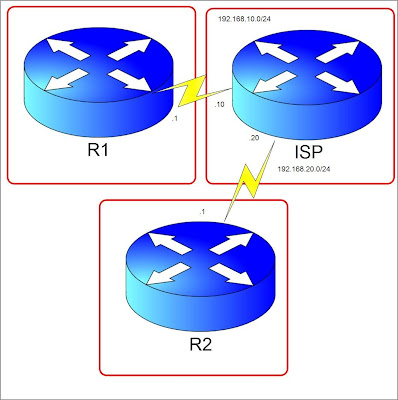
IPSEC VPN's have revolutionized the networking world. It is usually used over the unsecured network called "the Internet". It's a way to ensure secure transfer of data over the internet and used for site to site connections and telecommuters who need remote access from anywhere to the corporate Intranet or for remote branch offices that only have internet connection. We have a basic diagram below and lets configure a Site to Site IPSEC VPN. We will focus more on configuration not on the nitty gritty details of the protocols and the process of VPN creation.


Let's pretend ISP is the Internet Cloud. We have R1 and R2 connected through an internet leased line to their ISP's. Lets say R2 has a server 2.2.2.2 which R1 needs to access from 1.1.1.1 in its network. (1.1.1.1 and 2.2.2.2 are just loopback addresses in R1 and R2 respectively) We will build a VPN tunnel allowing 1.1.1.1 to access 2.2.2.2 and vice versa. Steps are numbered but not necessarily the standard way but a more favorable way of configuring.


1. Create an access-list on both R1 and R2. This will indicate the "interesting traffic". This means that anything that matches the ACL applied to the tunnel configuration will pass through the tunnel instead of exiting the interface facing the internet.


R1(config)#access-list 100 permit ip host 1.1.1.1 host 2.2.2.2
R2(config)#access-list 100 permit ip host 2.2.2.2 host 1.1.1.1

Notice that the ACL's mirror each other.

2. Configure an ISAKMP key. This key will be used to generate more keys for VPN tunnel creation and must match between the peers.


R1(config)#crypto isakmp key 0 myvpnrouter address 192.168.20.1
R2(config)#crypto isakmp key 0 myvpnrouter address 192.168.10.1

The ip address at the end of the command is the IP address of the peer router.

3. Create an ISAKMP policy. The policy components like hashing, authentication, Diffie-Helman group, and lifetime must match. You can configure many different policies and the routers will check the ISAKMP policy until it finds a match of its own. It is checked sequentially by using policy sequence numbers. ISAKMP negotiation is also called Phase 1.


R1(config-isakmp)#crypto isakmp policy 10
R1(config-isakmp)#group 2
R1(config-isakmp)#hash md5
R1(config-isakmp)#lifetime 28800
R1(config-isakmp)#encryption aes
R1(config-isakmp)#authentication pre-share

R2(config-isakmp)#crypto isakmp policy 10

R2(config-isakmp)#group 2
R2(config-isakmp)#hash md5
R2(config-isakmp)#lifetime 28800
R2(config-isakmp)#encryption aes
R2(config-isakmp)#authentication pre-share

4. Configure Phase 2 which are IPSEC parameters.


R1(config)#crypto ipsec transform-set TRANSFORMERS esp-3des esp-sha-hmac
R1(config)#crypto ipsec security-association lifetime seconds 28800
R2(config)#crypto ipsec transform-set TRANSFORMERS esp-3des esp-sha-hmac
R2(config)#crypto ipsec security-association lifetime seconds 28800

Configure a crypto map.


R1(config)#crypto map MYMAP 10 ipsec-isakmp
% NOTE: This new crypto map will remain disabled until a peer
and a valid access list have been configured.
R1(config-crypto-map)#match address 100
R1(config-crypto-map)#description to R2
R1(config-crypto-map)#set transform-set TRANSFORMERS
R1(config-crypto-map)#set peer 192.168.20.1
R1(config-crypto-map)#set security-association lifetime seconds 28800

R2(config)#crypto map MYMAP 10 ipsec-isakmp
% NOTE: This new crypto map will remain disabled until a peer
and a valid access list have been configured.
R2(config-crypto-map)#match address 100
R2(config-crypto-map)#description to R1
R2(config-crypto-map)#set transform-set TRANSFORMERS
R2(config-crypto-map)#set peer 192.168.10.1
R2(config-crypto-map)#set security-association lifetime seconds 28800

5. Apply the Crypto map to the outgoing interface.


R1(config)#int se1/1
R1(config-if)#crypto map MYMAP
R1(config-if)#
*Jul 11 13:05:47.007: %CRYPTO-6-ISAKMP_ON_OFF: ISAKMP is ON

R2(config)#int se1/2
R2(config-if)#crypto map MYMAP
R2(config-if)#
*Jul 11 13:05:47.007: %CRYPTO-6-ISAKMP_ON_OFF: ISAKMP is ON

6. Make sure you have a route towards the peer vpn router public ip. In our case lets create a default route.


R1(config)#ip route 0.0.0.0 0.0.0.0 192.168.10.10 name To_R2
R2(config)#ip route 0.0.0.0 0.0.0.0 192.168.20.20 name To_R1

7. Finally lets test the connection. The tunnel won't come up until there is interesting traffic passing through the tunnel. Any traffic that will hit the access-list we matched in the crypto-map will trigger the tunnel negotiation. In our case lets ping 2.2.2.2 from R1 sourcing from the Loopback interface 1.1.1.1. In the ISP router, I have configured a route for the 2 loopback addresses.


ISP(config)#ip route 2.2.2.2 255.255.255.255 192.168.20.1
ISP(config)#ip route 1.1.1.1 255.255.255.255 192.168.10.1

R1#ping 2.2.2.2 source 1.1.1.1

Type escape sequence to abort.
Sending 5, 100-byte ICMP Echos to 2.2.2.2, timeout is 2 seconds:
Packet sent with a source address of 1.1.1.1
!!!!!

To verify if the tunnel is up and running, lets use the "show crypto isakmp sa" to check Phase 1 status.


R1#sh cry isakmp sa
dst src state conn-id slot status
192.168.20.1 192.168.10.1 QM_IDLE 1 0 ACTIVE

QM_IDLE means that the tunnel is up. If the state is not that, that means that there is a problem.

"Show crypto ipsec sa" displays Phase 2 information which includes the number of packets that used the tunnel and the source and destination IP. Thats it for the configuration. For more detailed information on the VPN negotiation process visit this link. Cheers

Certifications

Certifications

The Dreamer

A fun loving person who enjoys learning new things. Currently working as a Network Engineer supporting the global network of a Fortune 500 company. This blog serves as my notes for the labs I created for my CCIE journey. I can guarantee there are errors in my posts. If you spot them, please let me know.

Join my Facebook Page I WANT TO BE A CCIE

Donate to the Cause

My aim is to create materials for free and possibly a free lab. If you wish to help out, please send any amount. Thanks.

Join my Bandwagon

Blogs that I Read