Q: What is the range of the Private AS numbers allocated by IANA?
Highlight after < for the answer.
A: <IANA has reserved AS64512 through to AS65535 to be used as private ASNs
For more information on this visit this page:
http://www.apnic.net/services/services-apnic-provides/helpdesk/faqs/asn-faqs
BGP Remove-Private-AS
Most companies have acquired their own AS number and also some have implemented Private AS numbers connected to their Public AS network. They might have created a private AS number per region. There are others also who run BGP and are using private AS connected to their ISP using PA (Provider Allocated) Public IP addresses. No matter, how its implemented, announcing the private AS number you are using to the internet is a big NO, NO. ISP's should filter these private AS and not advertise them out to the internet.
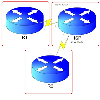
Consider the diagram below. Let's say R1 is in Company A and is connected to its ISP using a private AS number 65535. The task we need to complete here is to filter any private AS to be announced to R2 so that R2 will only see the AS number of the ISP.

Firstly, I have done configuring the IP addresses indicated in the diagram. Created Loopback0 and Loopback10 in R1 and ISP and advertised them in BGP. Of course, all routers have BGP established. I have also announced networks 123.123.123.123/32 and 12.12.12.12/32 in the ISP router.
Now, lets check what R2 sees in the BGP table.
We see that the AS path to get to 1.1.1.1/32 and 11.11.11.11/32 is through AS 100 then AS65535. Lets do a filtering in ISP router not to advertise this private AS but instead make the ISP's AS the originating AS.
The "remove-private-as" appended to the neighbor statement ensures that any private AS connected to the ISP will not appear in the AS path. Lets clear the BGP process by doing "clear ip bgp * soft" on ISP router and see what R2 BGP table.
The networks from R1 now is seen originated from AS 100. The private AS number was removed by the command we issued. Note that this command works in the outbound direction and should be placed on the networks with public AS number but have private AS connected to them. I tried this command on R2 before I added in ISP but I didn't work because like what I mentioned, this works in the outbound direction. Lab is done, proceeding to the next one or perhaps I might reading some cool mangas like my favorite One Piece! :)
Consider the diagram below. Let's say R1 is in Company A and is connected to its ISP using a private AS number 65535. The task we need to complete here is to filter any private AS to be announced to R2 so that R2 will only see the AS number of the ISP.

Firstly, I have done configuring the IP addresses indicated in the diagram. Created Loopback0 and Loopback10 in R1 and ISP and advertised them in BGP. Of course, all routers have BGP established. I have also announced networks 123.123.123.123/32 and 12.12.12.12/32 in the ISP router.
Now, lets check what R2 sees in the BGP table.
R2#sh ip bgp
BGP table version is 5, local router ID is 192.168.20.1
Status codes: s suppressed, d damped, h history, * valid, > best, i - internal,
              r RIB-failure, S Stale
Origin codes: i - IGP, e - EGP, ? - incomplete

   Network          Next Hop            Metric LocPrf Weight Path
*> 1.1.1.1/32       192.168.20.20                          0 100 65535 i
*> 11.11.11.11/32   192.168.20.20                          0 100 65535 i
*> 12.12.12.12/32   192.168.20.20            0             0 100 i
*> 123.123.123.123/32
                    192.168.20.20            0             0 100 i
We see that the AS path to get to 1.1.1.1/32 and 11.11.11.11/32 is through AS 100 then AS65535. Lets do a filtering in ISP router not to advertise this private AS but instead make the ISP's AS the originating AS.
ISP(config)#router bgp 100
ISP(config-router)#neighbor 192.168.20.1 remove-private-as
The "remove-private-as" appended to the neighbor statement ensures that any private AS connected to the ISP will not appear in the AS path. Lets clear the BGP process by doing "clear ip bgp * soft" on ISP router and see what R2 BGP table.
R2#sh ip bgp
BGP table version is 7, local router ID is 192.168.20.1
Status codes: s suppressed, d damped, h history, * valid, > best, i - internal,
              r RIB-failure, S Stale
Origin codes: i - IGP, e - EGP, ? - incomplete

   Network          Next Hop            Metric LocPrf Weight Path
*> 1.1.1.1/32       192.168.20.20                          0 100 i
*> 11.11.11.11/32   192.168.20.20                          0 100 i
*> 12.12.12.12/32   192.168.20.20            0             0 100 i
*> 123.123.123.123/32
                    192.168.20.20            0             0 100 i
The networks from R1 now is seen originated from AS 100. The private AS number was removed by the command we issued. Note that this command works in the outbound direction and should be placed on the networks with public AS number but have private AS connected to them. I tried this command on R2 before I added in ISP but I didn't work because like what I mentioned, this works in the outbound direction. Lab is done, proceeding to the next one or perhaps I might reading some cool mangas like my favorite One Piece! :)
Question of the Day: July 29, 2009
Q: In BGP dampening, what is the default value of the "reuse-value"?
Highlight after < for the answer.
A: <750
For more information on this visit this page:
http://www.avici.com/documentation/HTMLDocs/02223-06_revBA/BGP_Nd7.html
Highlight after < for the answer.
A: <750
For more information on this visit this page:
http://www.avici.com/documentation/HTMLDocs/02223-06_revBA/BGP_Nd7.html
Question of the Day: July 28, 2009
Q: In BGP dampening, how much is the per-flap penalty points?
Highlight after < for the answer.
A: <1000
For more information on this visit this page:
http://www.avici.com/documentation/HTMLDocs/02223-06_revBA/BGP_Nd7.html
Highlight after < for the answer.
A: <1000
For more information on this visit this page:
http://www.avici.com/documentation/HTMLDocs/02223-06_revBA/BGP_Nd7.html
Question of the Day: July 27, 2009
Q: By default, BGP can perform load balancing over how many parallel links?
Highlight after < for the answer.
A: < One. You can change the number of parallel links by the "maximum-paths" command.
For more information on this visit this page:
http://www.avici.com/documentation/HTMLDocs/02223-10_revAB/BGP_Nd22.html
Highlight after < for the answer.
A: < One. You can change the number of parallel links by the "maximum-paths" command.
For more information on this visit this page:
http://www.avici.com/documentation/HTMLDocs/02223-10_revAB/BGP_Nd22.html
Question of the Day: July 26, 2009
Q: What is required for the command "default-information originate" to work?
Highlight after < for the answer.
A: <For the router to advertise itself as a default route to the other routers, it must have its own default route configured statically or learned dynamically. Adding the keyword "always" will force the router to advertise itself as a default route even if there is no default route learned by the advertising router.
For more information on this visit this page:
http://www.avici.com/documentation/HTMLDocs/02223-10_revAB/ospf8.html
VRF and VRF-lite
I remembered that several months ago, I had an implementation regarding VRF-lite. In my previous posts VRF Basics and MPLS VPN VRF Select I haven't actually mentioned about VRF-lite. What exactly is this and how does this differ with VRF used in MPLS VPN?
First, ask the question, what is required to run VRF in the MPLS VPN implementation? Of course VRF, MP-BGP and MPLS should be running on the Provider's routers. It would need BGP VPNv4 neighborship to make MPLS VPN run.
VRF-lite is normally VRF without MPLS. This is Cisco's way, of what is so called virtualization. This can be useful of course if the enterprise has networks of overlapping IP addresses or some segments they don't want to be reached by other segments. Its kinda like VLAN in the sense that its in WAN. In this sense, VRF-lite configuration doesn't need the route-target part. For every VRF is a separate routing table. Routing VRF-lite can be done by static or dynamic under its vrf instance. I think I'll create a lab for this to show how it can be configured using IGP's. By the way, these days, I wonder why I am posting more on MPLS than any other topic? Does it mean I want to pursue CCIE SP than gettting the R&S? Good day! :)
Question of the Day: July 25, 2009
Q: What are the 5 STP switch port states?
Highlight after < for the answer.
A: <Blocking, Listening, Learning, Forwarding and Disabled
For more information on this visit this page:
http://en.wikipedia.org/wiki/Spanning_tree_protocol
Highlight after < for the answer.
A: <Blocking, Listening, Learning, Forwarding and Disabled
For more information on this visit this page:
http://en.wikipedia.org/wiki/Spanning_tree_protocol
Why CCIE?
So many have been asked the question why CCIE? Why not other certifications in networking? I have been asking myself the same question "why CCIE"? The second question is "is it worth getting a CCIE"?
Before I answer that trivial question, let me begin how I got into the Cisco world. I was hired as a contractor for AT&T and I had little knowledge about Cisco. Prior to that, I had Cisco experience by configuring Cisco DSL modems and the old Cisco routers like the 1700. During my training in AT&T, I met a CCIE for the first time and he showed us how good a CCIE is. That training sparked my interest in Cisco and from then on I started my path. A few months from that, I got my CCNA which I think was well worth because of that certification I landed a job in a good company who paid my CCNP fees.
Reminiscing about how my CCNP got me to where I am now, I have an idea how much more a CCIE cert will do to my career. If my CCNP got me a good job, how much more a CCIE. To answer the first question, "why CCIE?" The answer is because, I love the technology but more than that the driving force behind this motivation to get the cert is to give my family a better future. Being a CCIE, means you are an expert on what you doing. It means better job and a better life and it is a trademark of hardwork and perseverance. CCIE's also has a nice ring to it when someone calls you "hey Mr. CCIE".:)
Secondly, "is it worth it"? I think there is no need to ask this question. The answers from the first question should show that it is really worth it. I have known people who got CCIE and got better jobs and better exposure. My job currently is supporting and doing Change Management but imagine how exciting would it be if one was the expert and consultant of enterprises. It's a whole new level than my current job.
Thirdly, you might ask this question. Why Cisco Dreamer? Well, my goal is not only to be a CCIE but to work with Cisco as well. Simple and obvious isn't it? Good day!
Question of the Day: July 24, 2009
Q: What is default spanning-tree priority in Cisco switches?
Highlight after < for the answer.
A: <32768
For more information on this visit this page:
http://en.wikipedia.org/wiki/Spanning_tree_protocol
Highlight after < for the answer.
A: <32768
For more information on this visit this page:
http://en.wikipedia.org/wiki/Spanning_tree_protocol
Question of the Day: July 23, 2009
Q: Name the metrics used in EIGRP.
Highlight after < for the answer.
A: <Delay, Bandwidth, Reliability and Load. MTU is not being used in metric calculation but is considered a metric.
For more information on this visit this page:
http://www.rhyshaden.com/eigrp.htm
Highlight after < for the answer.
A: <Delay, Bandwidth, Reliability and Load. MTU is not being used in metric calculation but is considered a metric.
For more information on this visit this page:
http://www.rhyshaden.com/eigrp.htm
Question of the Day: July 22, 2009
Q: What is the name of a device in IS-IS that is similar to a DR in OSPF that flood hello packets in a broadcast media?
Highlight after < for the answer.
A: <Designated Intermediate System (DIS)
For more information on this visit this page:
http://en.wikipedia.org/wiki/IS-IS
Highlight after < for the answer.
A: <Designated Intermediate System (DIS)
For more information on this visit this page:
http://en.wikipedia.org/wiki/IS-IS
Question of the Day: July 21, 2009
Q: In EIGRP, what is a feasible successor?
Highlight after < for the answer.
A: <A Feasible Successor is a backup route to a destination which is kept in the Topology Table.
For more information on this visit this page:
http://www.rhyshaden.com/eigrp.htm
Highlight after < for the answer.
A: <A Feasible Successor is a backup route to a destination which is kept in the Topology Table.
For more information on this visit this page:
http://www.rhyshaden.com/eigrp.htm
MPLS VPN VRF Source Selection
It's been a while since I did some labs. Recently I received a comment from someone in the VRF Basics entry regarding importing the loopbacks from the CE routers to a VRF for management purposes. I'm in the middle of my BGP review but I'm curious anyway. I created a lab and tried a way and it seems I found a way how to. The feature is called VRF source selection, in which you can have multiple VRF's in an interface and VRF mapping is based on the source ip address. As we all know, CE routers usually don't have VRF's configured on them and usually for MPLS VPN setup one customer is assigned to one VRF. For MPLS Basics check my previous entry.
The diagram below shows 2 PE's and 3 CE's. I have preconfigured the PE's with BGP peering on both ipv4 and vpnv4 address-families and the necessary IP configuration with the CE's having a default route toward the directly connected PE. VPNv4 address-family on BGP by the way, is used for MPLS VPN. Configured MPLS on the link between PE1 and PE2.
Scenario:
We have 2 Customers, Customer1 and Customer2. The branch offices needs to connect to the other branches in PE2(I have created Loopback addresses for these). They need to have their own VRF's configured. Customer1 and Customer2 should have loopback0 ip addresses configured on the CE's for the NOC to use as management ip to access from their hopping server which is in ISP NOC router. VRF named "Management" should be used on the CE's. Customer's LAN networks are represented as Loopback10. The RD's of the Customers should be Customer1 - 1234:1, Customer2 - 1234:2 and Management - 1234:100. Click the image below for a bigger view.

The scenario requires 2 VRF's from every Customer CE. The Command "ip vrf forwarding" only uses one VRF per interface. We only have 1 interface and this command is not a feasible solution. We need to use VRF source selection in order to use multiple VRF's in an interface.
Provided that we already created the VRF's, first we would need to map a source IP address to a VRF. The PE will know which VRF a packet will be through the source IP.
After that, we would need to configure the interfaces in the PE's to use source selection. As mentioned, a while ago, "ip vrf forwarding" command is used if there is only one VRF used so in this scenario there is no need for the command.
The commands mean that on the corresponding interfaces the VRF are activated based on the "vrf selection source" commands. It's the equivalent of "ip Vrf forwarding" command but in the sense that its for multiple vrfs.
Well now the question is, how will the VRF's know which subnets will come from what interface. Simple, through routing.:) In our case since we are not configuring dynamic routing, we will configure static vrf routes.
It's obvious that the "vrf" keyword there points to what VRF this route belongs to.:) MPLS VPN requires that the routes be learned by Multiprotocol BGP. Since these are static routes we need to redistribute them into BGP on the ipv4 VRF address-family. Output pasted below from the running config.
If you notice, we didn't redistribute it on the "ipv4" global address-family but instead we did it on their corresponding VRF address-families. We learned that VRF's are like separate routing tables in a single router, and that exactly is the reason why we advertise this in different address-families.
We are not done yet, remember we have 2 loopback's in PE2 representing the other sites of Customer1 and Customer2. Lets configure those.
Let's check the VRF routing tables on R1.
We can see the routes that should be there. Now let's test the Customer1 VRF first if we achieved our objective. It should be able to reach the network 111.111.111.111/32 in PE2.
Cool its working! We need to specify the source ip so that it will be in the correct VRF. Network 111.111.111.111/32 is in vrf Customer1, if we don't use a source ip, by default it will use the exit interface's ip address as the source and will not be using any vrf since we don't have a source selection mapping for that. Instead it will use the "global routing table" which doesn't have entries for 111.111.111.111/32. Let's see what happens.
As expected! Let's do a test for Customer2.
And for our final objective, the Loopback0 should be reachable through vrf "Management" from ISP NOC router. By the way, since we are only using one VRF for this, it was not necessary to use source selection. It's only for example sake!:) Now for the testing.
Success!!! Whew, I don't like long blog entries but sure this will be helpful for myself in case I forget this feature. More on route-target import and export next time. Cheers!
The diagram below shows 2 PE's and 3 CE's. I have preconfigured the PE's with BGP peering on both ipv4 and vpnv4 address-families and the necessary IP configuration with the CE's having a default route toward the directly connected PE. VPNv4 address-family on BGP by the way, is used for MPLS VPN. Configured MPLS on the link between PE1 and PE2.
Scenario:
We have 2 Customers, Customer1 and Customer2. The branch offices needs to connect to the other branches in PE2(I have created Loopback addresses for these). They need to have their own VRF's configured. Customer1 and Customer2 should have loopback0 ip addresses configured on the CE's for the NOC to use as management ip to access from their hopping server which is in ISP NOC router. VRF named "Management" should be used on the CE's. Customer's LAN networks are represented as Loopback10. The RD's of the Customers should be Customer1 - 1234:1, Customer2 - 1234:2 and Management - 1234:100. Click the image below for a bigger view.

The scenario requires 2 VRF's from every Customer CE. The Command "ip vrf forwarding" only uses one VRF per interface. We only have 1 interface and this command is not a feasible solution. We need to use VRF source selection in order to use multiple VRF's in an interface.
Provided that we already created the VRF's, first we would need to map a source IP address to a VRF. The PE will know which VRF a packet will be through the source IP.
PE1(config)#vrf selection source 1.1.1.1 255.255.255.255 vrf Management
PE1(config)#vrf selection source 2.2.2.2 255.255.255.255 vrf Management
PE1(config)#vrf selection source 11.11.11.11 255.255.255.255 vrf Customer1
PE1(config)#vrf selection source 22.22.22.22 255.255.255.255 vrf Customer2

PE2(config)#vrf selection source 3.3.3.3 255.255.255.255 vrf Management
After that, we would need to configure the interfaces in the PE's to use source selection. As mentioned, a while ago, "ip vrf forwarding" command is used if there is only one VRF used so in this scenario there is no need for the command.
PE1(config)#interface Serial1/1
PE1(config-if)#ip vrf select source
PE1(config-if)#ip vrf receive Customer1
PE1(config-if)#ip vrf receive Management

PE1(config)#interface Serial1/2
PE1(config-if)#ip vrf select source
PE1(config-if)#ip vrf receive Customer2
PE1(config-if)#ip vrf receive Management

PE2(config)#interface Se1/3
PE2(config)#ip vrf select source
PE2(config)#ip vrf receive Management
The commands mean that on the corresponding interfaces the VRF are activated based on the "vrf selection source" commands. It's the equivalent of "ip Vrf forwarding" command but in the sense that its for multiple vrfs.
Well now the question is, how will the VRF's know which subnets will come from what interface. Simple, through routing.:) In our case since we are not configuring dynamic routing, we will configure static vrf routes.
PE1(config)#ip route vrf Customer1 11.11.11.11 255.255.255.255 192.168.10.1
PE1(config)#ip route vrf Customer2 22.22.22.22 255.255.255.255 192.168.20.2
PE1(config)#ip route vrf Management 1.1.1.1 255.255.255.255 192.168.10.1
PE1(config)#ip route vrf Management 2.2.2.2 255.255.255.255 192.168.20.2

PE2(config)#ip route vrf Management 3.3.3.3 255.255.255.255 192.168.30.3
It's obvious that the "vrf
PE1
!
address-family ipv4
neighbor 10.10.10.2 activate
no auto-summary
no synchronization
exit-address-family
!
address-family vpnv4
neighbor 10.10.10.2 activate
neighbor 10.10.10.2 send-community extended
exit-address-family
!
address-family ipv4 vrf Management
redistribute static metric 1
no auto-summary  no synchronization
exit-address-family
!
address-family ipv4 vrf Customer2
redistribute static metric 1
 no auto-summary
no synchronization
exit-address-family
!
 address-family ipv4 vrf Customer1
redistribute static metric 1  no auto-summary  no synchronization  exit-address-family

PE2
!
 address-family ipv4 vrf Management
redistribute static metric 1
no auto-summary
no synchronization
exit-address-family
If you notice, we didn't redistribute it on the "ipv4" global address-family but instead we did it on their corresponding VRF address-families. We learned that VRF's are like separate routing tables in a single router, and that exactly is the reason why we advertise this in different address-families.
We are not done yet, remember we have 2 loopback's in PE2 representing the other sites of Customer1 and Customer2. Lets configure those.
Ok, now lets check BGP peering on the VPNv4 address family. The "show ip bgp vpnv4 all summary" command will display the summary of the prefixes learned through all the VRF's.
PE2
!
interface Loopback1
 ip vrf forwarding Customer1
 ip address 111.111.111.111 255.255.255.255
!
interface Loopback2
 ip vrf forwarding Customer2
 ip address 222.222.222.222 255.255.255.255

Now let's advertise this in BGP.
!
 address-family ipv4 vrf Customer2
 no auto-summary
 no synchronization
 network 222.222.222.222 mask 255.255.255.255
 exit-address-family
 !
 address-family ipv4 vrf Customer1
 no auto-summary
 no synchronization
 network 111.111.111.111 mask 255.255.255.255
 exit-address-family
PE1#sh ip bgp vpnv4 all sum | beg Neighbor
Neighbor        V    AS MsgRcvd MsgSent   TblVer  InQ OutQ Up/Down  State/PfxRcd
10.10.10.2      4  1234      93     106       15    0    0 01:14:47        3

PE2#sh ip bgp vpnv4 all sum | beg Neighbor
Neighbor        V    AS MsgRcvd MsgSent   TblVer  InQ OutQ Up/Down  State/PfxRcd
10.10.10.1      4  1234     106      93       20    0    0 01:14:56        4
Let's check the VRF routing tables on R1.
PE1#sh ip route vrf Customer1 | beg Gateway
Gateway of last resort is not set

C    192.168.10.0/24 is directly connected, Serial1/1
     111.0.0.0/32 is subnetted, 1 subnets
B       111.111.111.111 [200/0] via 10.10.10.2, 00:23:02
     11.0.0.0/32 is subnetted, 1 subnets
S       11.11.11.11 [1/0] via 192.168.10.1
PE1#sh ip route vrf Customer2 | beg Gateway
Gateway of last resort is not set

     222.222.222.0/32 is subnetted, 1 subnets
B       222.222.222.222 [200/0] via 10.10.10.2, 00:24:04
     22.0.0.0/32 is subnetted, 1 subnets
S       22.22.22.22 [1/0] via 192.168.20.2
C    192.168.20.0/24 is directly connected, Serial1/2
PE1#sh ip route vrf Management | beg Gateway
Gateway of last resort is not set

     1.0.0.0/32 is subnetted, 1 subnets
S       1.1.1.1 [1/0] via 192.168.10.1
     2.0.0.0/32 is subnetted, 1 subnets
S       2.2.2.2 [1/0] via 192.168.20.2
     3.0.0.0/32 is subnetted, 1 subnets
B       3.3.3.3 [200/1] via 10.10.10.2, 01:02:10
C    192.168.10.0/24 is directly connected, Serial1/1
C    192.168.20.0/24 is directly connected, Serial1/2
We can see the routes that should be there. Now let's test the Customer1 VRF first if we achieved our objective. It should be able to reach the network 111.111.111.111/32 in PE2.
Customer1#ping 111.111.111.111 source 11.11.11.11

Type escape sequence to abort.
Sending 5, 100-byte ICMP Echos to 111.111.111.111, timeout is 2 seconds:
Packet sent with a source address of 11.11.11.11
!!!!!
Success rate is 100 percent (5/5), round-trip min/avg/max = 144/168/192 ms
Cool its working! We need to specify the source ip so that it will be in the correct VRF. Network 111.111.111.111/32 is in vrf Customer1, if we don't use a source ip, by default it will use the exit interface's ip address as the source and will not be using any vrf since we don't have a source selection mapping for that. Instead it will use the "global routing table" which doesn't have entries for 111.111.111.111/32. Let's see what happens.
Customer1#ping 111.111.111.111

Type escape sequence to abort.
Sending 5, 100-byte ICMP Echos to 111.111.111.111, timeout is 2 seconds:
U.U.U
Success rate is 0 percent (0/5)
As expected! Let's do a test for Customer2.
Customer2#ping 222.222.222.222 source 22.22.22.22

Type escape sequence to abort.
Sending 5, 100-byte ICMP Echos to 222.222.222.222, timeout is 2 seconds:
Packet sent with a source address of 22.22.22.22
!!!!!
Success rate is 100 percent (5/5), round-trip min/avg/max = 144/173/192 ms
And for our final objective, the Loopback0 should be reachable through vrf "Management" from ISP NOC router. By the way, since we are only using one VRF for this, it was not necessary to use source selection. It's only for example sake!:) Now for the testing.
ISPNOC#ping 1.1.1.1 source 3.3.3.3

Type escape sequence to abort.
Sending 5, 100-byte ICMP Echos to 1.1.1.1, timeout is 2 seconds:
Packet sent with a source address of 3.3.3.3
!!!!!
Success rate is 100 percent (5/5), round-trip min/avg/max = 172/216/264 ms
ISPNOC#ping 2.2.2.2 source 3.3.3.3

Type escape sequence to abort.
Sending 5, 100-byte ICMP Echos to 2.2.2.2, timeout is 2 seconds:
Packet sent with a source address of 3.3.3.3
!!!!!
Success rate is 100 percent (5/5), round-trip min/avg/max = 168/231/292 ms
Success!!! Whew, I don't like long blog entries but sure this will be helpful for myself in case I forget this feature. More on route-target import and export next time. Cheers!
Question of the Day: July 20, 2009
Q: What are the three tables EIGRP uses to store data?
Highlight after < for the answer.
A: < Neighbor Table, Topology Table, Routing Table
For more information on this visit this page:
http://en.wikipedia.org/wiki/Enhanced_Interior_Gateway_Routing_Protocol
Highlight after < for the answer.
A: < Neighbor Table, Topology Table, Routing Table
For more information on this visit this page:
http://en.wikipedia.org/wiki/Enhanced_Interior_Gateway_Routing_Protocol
Question of the Day: July 19, 2009
Q: Name the OSPF Neighbor States.
Highlight after < for the answer.
A: < Down,Attempt,Init,Two-Way(2way),Exstart,Exchange,Loading,Full
For more information on this visit this page:
http://www.cisco.com/en/US/tech/tk365/technologies_tech_note09186a0080093f0e.shtml
Highlight after < for the answer.
A: < Down,Attempt,Init,Two-Way(2way),Exstart,Exchange,Loading,Full
For more information on this visit this page:
http://www.cisco.com/en/US/tech/tk365/technologies_tech_note09186a0080093f0e.shtml
Question of the Day: July 18, 2009
Q: How many BGP processes can you run in a Cisco router?
Highlight after < for the answer.
A: <Only one process
Highlight after < for the answer.
A: <Only one process
Question of the Day: July 17, 2009
Q: What are the differences between DOT1Q and ISL?
Highlight after < for the answer.
A: < 1. Dot1q is IEEE standard, ISL is Cisco-proprietary. 2. Dot1q has the concept of a Native VLAN which doesn't tag the native vlan, ISL does not, it encapsulates all frames. 3. Dot1q tags the frame, ISL encapsulates it.
For more information on this visit this page:
http://www.thebryantadvantage.com/CCNACertificationExamWhySwitchesTrunkAndHow.htm
BGP AS-Path Prepending
BGP is rich in features that you can have more control than on what IGP's offer however, you can only have control on how the traffic leaves your autonomous system and can't really control how other autonomous systems reach you. Other AS'es might have BGP policies that route the traffic in a way you don't intend it to go. You don't have control over those because, its their autonomous systems after all. However, there are work arounds which allow, an autonomous system affect the other autonomous systems, one of this is called BGP AS-path prepending. It is basically adding additional AS-paths by repeating your own AS number. Consider the diagram below. (Click image for a bigger view) By looking at the diagram, if you are familiar with BGP, the AS-path the networks from R4 will take towards R1 will be AS4, AS3 and then AS1. If all the attributes are set to the default values, most likely the AS-path attribute will determine which path to take. The more desirable path in this scenario is AS4, AS3, AS2 and then AS1 for the reason that there is a 100mbps link connecting AS1 and AS2 which makes traffic forwarding more efficient. But remember, unlike IGP's, BGP doesn't take to account the bandwidth.
In this scenario we are in AS1 and we make AS2 the more desirable path for AS4 to reach us using AS-path prepending.

Checking on R4 we will see how it gets to R1.
Just as we guessed, it would take AS3 then AS1 which is the shortest path based on BGP attributes. Now we will configure AS-prepending on R1 for R4 to take the AS3, AS2 then AS1 path.
We made it 1 1 1 cause it would only 2 AS paths to reach R1 from R4 through R3. We will make that AS-path longer and less desirable. We will apply this route map we created to the neighborship peering between R1 and R3.
The reason its in the outbound direction because R1 is advertising the subnets. Let's clear the bgp process in R1 to make the changes. Then lets see what happened to the AS-path in R4.
Ok, you can see the difference now, its now taking 3-2-1. This is because it received an advertisement from R3 about the best path. BGP only advertises the best path to a network to its neighbor. Since R3 is seeing the AS_Path going to R1 is longer, it now takes AS2 to get to R1. Lets see what happened to the BGP table after applying the route map.
Three 1's were added to the AS_Path based on what we put on the route-map, so from the AS-path values, R3 will not go directly to R1 but will take R2 now instead.
Now what if we want traffic to 11.11.11.11 to take A3 directly and traffic to 1.1.1.1 take AS3 then AS2 from R4. We will create an access-list TAKER2 and modify the route-map to match the condition.
Let's check what happened to R3
Cool, you can see the difference with the ACL. Now 1.1.1.1 in R3 has prepend but 11.11.11.11 has no prepend. Finally, lets check R4.
From R4 traffic to 1.1.1.1 will pass through AS2 but to 11.11.11.11 it will go directly to R3 then R1. Whew, kinda hard to explain. Enough is enough! Cheers! :)
In this scenario we are in AS1 and we make AS2 the more desirable path for AS4 to reach us using AS-path prepending.

Checking on R4 we will see how it gets to R1.
R4#
*Jul 16 13:25:54.039: %SYS-5-CONFIG_I: Configured from console by console
R4#sh ip bgp
BGP table version is 11, local router ID is 34.34.34.4
Status codes: s suppressed, d damped, h history, * valid, > best, i - internal,
              r RIB-failure, S Stale
Origin codes: i - IGP, e - EGP, ? - incomplete

   Network          Next Hop            Metric LocPrf Weight Path
*> 1.1.1.1/32       34.34.34.3                             0 3 1 i
*> 4.4.4.4/32       0.0.0.0                  0         32768 i
*> 11.11.11.11/32   34.34.34.3                             0 3 1 i
*> 44.44.44.44/32   0.0.0.0                  0         32768 i
Just as we guessed, it would take AS3 then AS1 which is the shortest path based on BGP attributes. Now we will configure AS-prepending on R1 for R4 to take the AS3, AS2 then AS1 path.
R1(config)#route-map ASPREPEND permit 10
R1(config-route-map)#set as-path prepend 1 1 1
R1(config)#route-map ASPREPEND permit 20
We made it 1 1 1 cause it would only 2 AS paths to reach R1 from R4 through R3. We will make that AS-path longer and less desirable. We will apply this route map we created to the neighborship peering between R1 and R3.
R1(config)#router bgp 1
R1(config-router)#neighbor 13.13.13.3 route-map ASPREPEND out
The reason its in the outbound direction because R1 is advertising the subnets. Let's clear the bgp process in R1 to make the changes. Then lets see what happened to the AS-path in R4.
R4#sh ip bgp
BGP table version is 13, local router ID is 34.34.34.4
Status codes: s suppressed, d damped, h history, * valid, > best, i - internal,
              r RIB-failure, S Stale
Origin codes: i - IGP, e - EGP, ? - incomplete

   Network          Next Hop            Metric LocPrf Weight Path
*> 1.1.1.1/32       34.34.34.3                             0 3 2 1 i
*> 4.4.4.4/32       0.0.0.0                  0         32768 i
*> 11.11.11.11/32   34.34.34.3                             0 3 2 1 i
*> 44.44.44.44/32   0.0.0.0                  0         32768 i
Ok, you can see the difference now, its now taking 3-2-1. This is because it received an advertisement from R3 about the best path. BGP only advertises the best path to a network to its neighbor. Since R3 is seeing the AS_Path going to R1 is longer, it now takes AS2 to get to R1. Lets see what happened to the BGP table after applying the route map.
R3#sh ip bgp
BGP table version is 13, local router ID is 23.23.23.3
Status codes: s suppressed, d damped, h history, * valid, > best, i - internal,
              r RIB-failure, S Stale
Origin codes: i - IGP, e - EGP, ? - incomplete

   Network          Next Hop            Metric LocPrf Weight Path
*> 1.1.1.1/32       23.23.23.2                             0 2 1 i
*                   13.13.13.1               0             0 1 1 1 1 i
*> 4.4.4.4/32       34.34.34.4               0             0 4 i
*> 11.11.11.11/32   23.23.23.2                             0 2 1 i
*                   13.13.13.1               0             0 1 1 1 1 i
*> 44.44.44.44/32   34.34.34.4               0             0 4 i
Three 1's were added to the AS_Path based on what we put on the route-map, so from the AS-path values, R3 will not go directly to R1 but will take R2 now instead.
Now what if we want traffic to 11.11.11.11 to take A3 directly and traffic to 1.1.1.1 take AS3 then AS2 from R4. We will create an access-list TAKER2 and modify the route-map to match the condition.
R1(config)#ip access-list extended TAKER2
R1(config-ext-nacl)#permit ip host 1.1.1.1 any

R1(config)#route-map ASPREPEND permit 10
R1(config-route-map)#match ip address TAKER2
R1(config-route-map)#set as-path prepend 1 1 1
Let's check what happened to R3
R3#sh ip bgp
BGP table version is 28, local router ID is 23.23.23.3
Status codes: s suppressed, d damped, h history, * valid, > best, i - internal,
              r RIB-failure, S Stale
Origin codes: i - IGP, e - EGP, ? - incomplete

   Network          Next Hop            Metric LocPrf Weight Path
*> 1.1.1.1/32       23.23.23.2                             0 2 1 i
*                   13.13.13.1               0             0 1 1 1 1 i
*> 4.4.4.4/32       34.34.34.4               0             0 4 i
*  11.11.11.11/32   23.23.23.2                             0 2 1 i
*>                  13.13.13.1               0             0 1 i
*> 44.44.44.44/32   34.34.34.4               0             0 4 i
Cool, you can see the difference with the ACL. Now 1.1.1.1 in R3 has prepend but 11.11.11.11 has no prepend. Finally, lets check R4.
R4#sh ip bgp
BGP table version is 27, local router ID is 34.34.34.4
Status codes: s suppressed, d damped, h history, * valid, > best, i - internal,
              r RIB-failure, S Stale
Origin codes: i - IGP, e - EGP, ? - incomplete

   Network          Next Hop            Metric LocPrf Weight Path
*> 1.1.1.1/32       34.34.34.3                             0 3 2 1 i
*> 4.4.4.4/32       0.0.0.0                  0         32768 i
*> 11.11.11.11/32   34.34.34.3                             0 3 1 i
*> 44.44.44.44/32   0.0.0.0                  0         32768 i
From R4 traffic to 1.1.1.1 will pass through AS2 but to 11.11.11.11 it will go directly to R3 then R1. Whew, kinda hard to explain. Enough is enough! Cheers! :)
Question of the Day: July 16, 2009
Q: Into which of the BGP neighbor states must a neighbor stabilize before BGP Update messages may be sent?
Highlight after < for the answer.
A: < Established
For more information on this visit this page:
http://archive.networknewz.com/networknewz-10-20060403BGPAdjacencyStates.html
Highlight after < for the answer.
A: < Established
For more information on this visit this page:
http://archive.networknewz.com/networknewz-10-20060403BGPAdjacencyStates.html
Firewall Security-Level
This is my first Security Post regarding Cisco PIX/ASA firewalls. To begin with, what is a firewall? Literally, in the real world, a firewall as part of a building, is used to you guessed it: protect the building from fire. :) The same applies in the networking world. A firewall is a device that prevents unauthorized access and permits authorized access to a network. A firewall may function for packet filtering, proxy server and stateful packet filtering. Cisco PIX/ASA devices function as stateful packet filtering devices, which builds a stateful connection table to verify the connections.
A firewall prevents access from the untrusted network to the trusted network. An interface of the firewall may belong to the untrusted or the trusted. The interface that belongs to the trusted network is often called the inside interface and the untrusted one is the outside interface. Security-levels from 0-100 indicates the level of trust for an interface. The higher the number the more trusted the interface. The rule in security-level is that a higher security level can have access to a lower security level, the lower security level doesn't have access to a higher security level and is blocked by default. Interfaces with the same security levels are blocked as well.
Let's configure interfaces and lets see how security-levels are applied automatically and manually. I am using a PIX firewall.
First lets configure an outside interface.
The "nameif" command is basically used to name an interface. Very obvious isn't it?:) Notice that once we named the interface "outside", Cisco automatically set the security-level to 0 meaning its untrusted. Next we configure an inside interface.
The PIX now configures the security level by 100 which means its a trusted interface. For this reason, traffic from ethernet1 to ethernet0 is permitted by default but traffic from ethernet0 to ethernet1 is not. This is where inbound access-list comes in to allow traffic from an untrusted interface to a trusted one.
Let us now configure an interface named "webservers". You can use any name you like by the way. Let's give it a security-level of 60.
Notice that any interface name other than "inside" is automatically given a 0 security-level value. The "security-level" command is used to specify manually a security level to an interface. Ethernet2 by default can access Ethernet0 but can't access Ethernet1, because the latter has a higher security-level than the former. The "show nameif" command is a very useful command to display the names of the interfaces including the security-levels.
As you can see, in the PIX firewall the show command is accepted unlike in the routers which doesn't accept show commands in the global-configuration mode. For those have been configuring routers, adapting to configuring firewalls would be easy. After all, its still Cisco. :)
Finally, sometimes there is a need to allow access to interfaces with the same security-level. The command below, will allow such access.
There you have it. Its easy as one, two, three. Good day homies!
A firewall prevents access from the untrusted network to the trusted network. An interface of the firewall may belong to the untrusted or the trusted. The interface that belongs to the trusted network is often called the inside interface and the untrusted one is the outside interface. Security-levels from 0-100 indicates the level of trust for an interface. The higher the number the more trusted the interface. The rule in security-level is that a higher security level can have access to a lower security level, the lower security level doesn't have access to a higher security level and is blocked by default. Interfaces with the same security levels are blocked as well.
Let's configure interfaces and lets see how security-levels are applied automatically and manually. I am using a PIX firewall.
First lets configure an outside interface.
petesfirewall(config)# interface ethernet0
petesfirewall(config-if)# nameif outside
INFO: Security level for "outside" set to 0 by default.
The "nameif" command is basically used to name an interface. Very obvious isn't it?:) Notice that once we named the interface "outside", Cisco automatically set the security-level to 0 meaning its untrusted. Next we configure an inside interface.
petesfirewall(config-if)# interface ethernet1
petesfirewall(config-if)# nameif inside
INFO: Security level for "inside" set to 100 by default.
The PIX now configures the security level by 100 which means its a trusted interface. For this reason, traffic from ethernet1 to ethernet0 is permitted by default but traffic from ethernet0 to ethernet1 is not. This is where inbound access-list comes in to allow traffic from an untrusted interface to a trusted one.
Let us now configure an interface named "webservers". You can use any name you like by the way. Let's give it a security-level of 60.
petesfirewall(config-if)# interface ethernet2
petesfirewall(config-if)# nameif webservers
INFO: Security level for "webservers" set to 0 by default.
petesfirewall(config-if)# security-level 60
Notice that any interface name other than "inside" is automatically given a 0 security-level value. The "security-level" command is used to specify manually a security level to an interface. Ethernet2 by default can access Ethernet0 but can't access Ethernet1, because the latter has a higher security-level than the former. The "show nameif" command is a very useful command to display the names of the interfaces including the security-levels.
petesfirewall(config)# show nameif
Interface                Name                     Security
Ethernet0                outside                    0
Ethernet1                inside                   100
Ethernet2                webservers                60
As you can see, in the PIX firewall the show command is accepted unlike in the routers which doesn't accept show commands in the global-configuration mode. For those have been configuring routers, adapting to configuring firewalls would be easy. After all, its still Cisco. :)
Finally, sometimes there is a need to allow access to interfaces with the same security-level. The command below, will allow such access.
petesfirewall(config)# same-security-traffic permit inter-interface
There you have it. Its easy as one, two, three. Good day homies!
Question of the Day: July 15, 2009
Q: What is the IEEE standard that defines Fasthernet standard?
Highlight after < for the answer.
A: <IEEE 802.3u
For more information on this visit this page:
http://www.javvin.com/protocolFastE.html
Highlight after < for the answer.
A: <IEEE 802.3u
For more information on this visit this page:
http://www.javvin.com/protocolFastE.html
Question of the Day: July 14, 2009
Q: What is the algorithm used in link-state protocols to calculate the best path?
Highlight after < for the answer.
A: < Dijkstra's Algorithm
For more information on this visit this page:
http://en.wikipedia.org/wiki/Link-state_routing_protocol
Highlight after < for the answer.
A: < Dijkstra's Algorithm
For more information on this visit this page:
http://en.wikipedia.org/wiki/Link-state_routing_protocol
Question of the Day: July 13, 2009
Q: What is the default security-level of a PIX/ASA outside interface?
Highlight after < for the answer.
A: < Zero (0)
Highlight after < for the answer.
A: < Zero (0)
Question of the Day: July 12, 2009
Q: What are the 4 categories of BGP Attributes?
Highlight after < for the answer.
A: < 1) Well-known Mandatory 2) Well-known Discretionary 3) Optional Transitive 4) Optional Non-transitive
For more information on this visit this page:
http://www.brainbuzz.com/articles/files/border-gateway-protocol-a-982003-1304.asp
Highlight after < for the answer.
A: < 1) Well-known Mandatory 2) Well-known Discretionary 3) Optional Transitive 4) Optional Non-transitive
For more information on this visit this page:
http://www.brainbuzz.com/articles/files/border-gateway-protocol-a-982003-1304.asp
IPSEC VPN Configuration
IPSEC VPN's have revolutionized the networking world. It is usually used over the unsecured network called "the Internet". It's a way to ensure secure transfer of data over the internet and used for site to site connections and telecommuters who need remote access from anywhere to the corporate Intranet or for remote branch offices that only have internet connection. We have a basic diagram below and lets configure a Site to Site IPSEC VPN. We will focus more on configuration not on the nitty gritty details of the protocols and the process of VPN creation.
Let's pretend ISP is the Internet Cloud. We have R1 and R2 connected through an internet leased line to their ISP's. Lets say R2 has a server 2.2.2.2 which R1 needs to access from 1.1.1.1 in its network. (1.1.1.1 and 2.2.2.2 are just loopback addresses in R1 and R2 respectively) We will build a VPN tunnel allowing 1.1.1.1 to access 2.2.2.2 and vice versa. Steps are numbered but not necessarily the standard way but a more favorable way of configuring.
1. Create an access-list on both R1 and R2. This will indicate the "interesting traffic". This means that anything that matches the ACL applied to the tunnel configuration will pass through the tunnel instead of exiting the interface facing the internet.
Notice that the ACL's mirror each other.
2. Configure an ISAKMP key. This key will be used to generate more keys for VPN tunnel creation and must match between the peers.
The ip address at the end of the command is the IP address of the peer router.
3. Create an ISAKMP policy. The policy components like hashing, authentication, Diffie-Helman group, and lifetime must match. You can configure many different policies and the routers will check the ISAKMP policy until it finds a match of its own. It is checked sequentially by using policy sequence numbers. ISAKMP negotiation is also called Phase 1.
4. Configure Phase 2 which are IPSEC parameters.
Configure a crypto map.
5. Apply the Crypto map to the outgoing interface.
6. Make sure you have a route towards the peer vpn router public ip. In our case lets create a default route.
7. Finally lets test the connection. The tunnel won't come up until there is interesting traffic passing through the tunnel. Any traffic that will hit the access-list we matched in the crypto-map will trigger the tunnel negotiation. In our case lets ping 2.2.2.2 from R1 sourcing from the Loopback interface 1.1.1.1. In the ISP router, I have configured a route for the 2 loopback addresses.
To verify if the tunnel is up and running, lets use the "show crypto isakmp sa" to check Phase 1 status.
QM_IDLE means that the tunnel is up. If the state is not that, that means that there is a problem.
"Show crypto ipsec sa" displays Phase 2 information which includes the number of packets that used the tunnel and the source and destination IP. Thats it for the configuration. For more detailed information on the VPN negotiation process visit this link. Cheers

Let's pretend ISP is the Internet Cloud. We have R1 and R2 connected through an internet leased line to their ISP's. Lets say R2 has a server 2.2.2.2 which R1 needs to access from 1.1.1.1 in its network. (1.1.1.1 and 2.2.2.2 are just loopback addresses in R1 and R2 respectively) We will build a VPN tunnel allowing 1.1.1.1 to access 2.2.2.2 and vice versa. Steps are numbered but not necessarily the standard way but a more favorable way of configuring.
1. Create an access-list on both R1 and R2. This will indicate the "interesting traffic". This means that anything that matches the ACL applied to the tunnel configuration will pass through the tunnel instead of exiting the interface facing the internet.
R1(config)#access-list 100 permit ip host 1.1.1.1 host 2.2.2.2
R2(config)#access-list 100 permit ip host 2.2.2.2 host 1.1.1.1
Notice that the ACL's mirror each other.
2. Configure an ISAKMP key. This key will be used to generate more keys for VPN tunnel creation and must match between the peers.
R1(config)#crypto isakmp key 0 myvpnrouter address 192.168.20.1
R2(config)#crypto isakmp key 0 myvpnrouter address 192.168.10.1
The ip address at the end of the command is the IP address of the peer router.
3. Create an ISAKMP policy. The policy components like hashing, authentication, Diffie-Helman group, and lifetime must match. You can configure many different policies and the routers will check the ISAKMP policy until it finds a match of its own. It is checked sequentially by using policy sequence numbers. ISAKMP negotiation is also called Phase 1.
R1(config-isakmp)#crypto isakmp policy 10
R1(config-isakmp)#group 2
R1(config-isakmp)#hash md5
R1(config-isakmp)#lifetime 28800
R1(config-isakmp)#encryption aes
R1(config-isakmp)#authentication pre-share

R2(config-isakmp)#crypto isakmp policy 10
R2(config-isakmp)#group 2
R2(config-isakmp)#hash md5
R2(config-isakmp)#lifetime 28800
R2(config-isakmp)#encryption aes
R2(config-isakmp)#authentication pre-share
4. Configure Phase 2 which are IPSEC parameters.
R1(config)#crypto ipsec transform-set TRANSFORMERS esp-3des esp-sha-hmac
R1(config)#crypto ipsec security-association lifetime seconds 28800
R2(config)#crypto ipsec transform-set TRANSFORMERS esp-3des esp-sha-hmac
R2(config)#crypto ipsec security-association lifetime seconds 28800
Configure a crypto map.
R1(config)#crypto map MYMAP 10 ipsec-isakmp
% NOTE: This new crypto map will remain disabled until a peer
        and a valid access list have been configured.
R1(config-crypto-map)#match address 100
R1(config-crypto-map)#description to R2
R1(config-crypto-map)#set transform-set TRANSFORMERS
R1(config-crypto-map)#set peer 192.168.20.1
R1(config-crypto-map)#set security-association lifetime seconds 28800

R2(config)#crypto map MYMAP 10 ipsec-isakmp
 % NOTE: This new crypto map will remain disabled until a peer
         and a valid access list have been configured.
R2(config-crypto-map)#match address 100
R2(config-crypto-map)#description to R1
R2(config-crypto-map)#set transform-set TRANSFORMERS
R2(config-crypto-map)#set peer 192.168.10.1
R2(config-crypto-map)#set security-association lifetime seconds 28800
5. Apply the Crypto map to the outgoing interface.
R1(config)#int se1/1
R1(config-if)#crypto map MYMAP
R1(config-if)#
*Jul 11 13:05:47.007: %CRYPTO-6-ISAKMP_ON_OFF: ISAKMP is ON

R2(config)#int se1/2
R2(config-if)#crypto map MYMAP
R2(config-if)#
*Jul 11 13:05:47.007: %CRYPTO-6-ISAKMP_ON_OFF: ISAKMP is ON
6. Make sure you have a route towards the peer vpn router public ip. In our case lets create a default route.
R1(config)#ip route 0.0.0.0 0.0.0.0 192.168.10.10 name To_R2
R2(config)#ip route 0.0.0.0 0.0.0.0 192.168.20.20 name To_R1
7. Finally lets test the connection. The tunnel won't come up until there is interesting traffic passing through the tunnel. Any traffic that will hit the access-list we matched in the crypto-map will trigger the tunnel negotiation. In our case lets ping 2.2.2.2 from R1 sourcing from the Loopback interface 1.1.1.1. In the ISP router, I have configured a route for the 2 loopback addresses.
ISP(config)#ip route 2.2.2.2 255.255.255.255 192.168.20.1
ISP(config)#ip route 1.1.1.1 255.255.255.255 192.168.10.1

R1#ping 2.2.2.2 source 1.1.1.1

Type escape sequence to abort.
Sending 5, 100-byte ICMP Echos to 2.2.2.2, timeout is 2 seconds:
Packet sent with a source address of 1.1.1.1
!!!!!
To verify if the tunnel is up and running, lets use the "show crypto isakmp sa" to check Phase 1 status.
R1#sh cry isakmp sa
dst             src             state          conn-id slot status
192.168.20.1    192.168.10.1    QM_IDLE              1    0 ACTIVE
QM_IDLE means that the tunnel is up. If the state is not that, that means that there is a problem.
"Show crypto ipsec sa" displays Phase 2 information which includes the number of packets that used the tunnel and the source and destination IP. Thats it for the configuration. For more detailed information on the VPN negotiation process visit this link. Cheers
Question of the Day: July 11, 2009
Q: What is a virtual link?
Highlight after < for the answer.
A: < All areas in an OSPF autonomous system must be physically connected to the backbone area (area 0). In some cases where this physical connection is not possible, you can use a virtual link to connect to the backbone through a non-backbone area. As mentioned above, you can also use virtual links to connect two parts of a partitioned backbone through a non-backbone area. The area through which you configure the virtual link, known as a transit area, must have full routing information. The transit area cannot be a stub area.
For more information on virtual-links visit this page:
http://www.cisco.com/en/US/tech/tk365/technologies_configuration_example09186a00801ec9ee.shtml
Question of the Day Portion
Its been a while since I last posted an entry. I have been doing some reading and I feel that for the mastery of the topics, a question of the day portion would be very nice. CCIE Pursuit blog shows some excellent Question of the day portion which I think would be good for my blog. All credit goes to CCIE Pursuit blog for this idea! From here own, I'll start the question of the day.
Certifications

Blogs that I Read
-
-
-
-
IPv6 radius accounting is still a mess - Since the beginning of putting IPv6 into production BRAS/BNG (almost 3 years ago), we were facing the following issue: radius accounting records were missi...12 years ago
-
Internetwork Expert Volume IV (Troubleshooting) Workbook Review: Part 3 - Once you get the initial configurations loaded you’re ready to begin the lab. This is when the “fun” begins. Those of us who are used to starting labs wi...16 years ago
-
-
Cavani Authorize Central Approached Atletico Madrid Squad - Atletico Madrid Squad – PSG striker Edinson Cavani, incredulously, if he is a similar player Luis Suarez, though they are both from Uruguay. CAVANI will be...9 years ago
-
Network Engineer Jobs - So you want to work for Google as Network Engineer? Check out one of the job ads here. I pasted the screenshot below just in case the ad is removed once...8 years ago
-
Interested in Microsoft Azure? Tune into James Rudley’s Newest Course - Get ready to explore the different methods of automating technical and business challenges with Azure in James Rudley’s new course; Automation With Microso...7 years ago
-
130 Years of Wireless Communications - Here’s a short glimpse into the history of telecommunications: in a building at the top of this mountain (barely noticeable blip across the saddle from t...2 days ago
-
Clearing the fog around open switching terminology - The networking industry is making a decisive move toward open switches. Much of the media's attention is on mega-scale operators' do-it-yourself switche...10 years ago
-
-
A Short Summary of Planes - A Short Summary of Planes (the network kind) When the CCDE program was first developed, Cisco conveniently broke down the included technologies into five...7 years ago
-
Book Review: Model-Driven DevOps - Earlier this month at Cisco Live in Las Vegas, I attended a presentation by Steven Carter and Jason King titled *Model-Driven DevOps: The Enterprise Auto...2 years ago
-
Data Center Study - Notes 01 - - reverse proxy caching - the user of loadbalancers for server health monitoring - the need for jumbo frames - the need for NIC features such as interrupt co...12 years ago
-
-
I’m Back - Well hello blog world. Yes it’s been a while since I last posted an update. I meant to update sooner but because I haven’t logged on to WordPress in such a...12 years ago
-
Integrating the Nexus 1000v VSM with vCenter - This is a follow-up to my previous post regarding the Nexus 1000v. Now that I help set the stage for what the Nexus 1000v really is, we can start looking a...16 years ago
-

